Ken Myers Change of ADDERESS!
Ken Myers
1911 Bradshaw Ct.
Walled Lake, MI 48390
Phone: 248-669-8124
Ampeer Paper Subscriber Reminder
When subscribing to or renewing the paper version of the Ampeer, please make the check payable to Ken Myers. We do not have a DBA for the Ampeer or EFO. Thanks, Ken
Connector Info
By Ken Myers
Last month I mentioned that I had had some difficulty in finding the right connector for measuring my Li-Po battery through the balance connector. I received a couple of emails to help others in their quest for connectors.
From Don "Doc" Mrozowicz
wa3itz@penn.com
Just read the November Ampeer and figured I would pass this information on to you just in case you are not familiar with this.
I buy connectors called headers with 0.1" spacing and gold plating. They come in a strip of 30 contacts, I cut them into 3, 4 or whatever number of pins I need with a RAZOR saw. I make up aileron extensions, servo connectors and they fit all new receivers, all Li-poly voltage monitoring jacks with 0.1" spacing. They are available from Mouser or Digi-Key for about $1.25 for the male and $2.00 for the female. I solder using a small iron, add shrink and have a better connector then anything on the R/C market. Just make sure you get Gold plated version. The male comes in different lengths.
Another good source for contactors for testing is old computer MB and plug in connector harnesses. If you need more info on buying let me know I can look up the numbers if you need them.
Have a good day and thanks for the hard work on the Ampeer.
From Jim Porter
airporter@mchsi.com
Hello Ken,
While reading the comments on battery connectors I realized that perhaps neither Ed Harris, who died in October 2000, nor myself had ever corresponded with you about the connectors we use/d with servos and auto hookup on plug-in/on wings. This is particularly appropriate after reading about the difficulties in finding useful connectors for monitoring Li-Po battery voltages.
Here are the numbers for the connectors I use on nearly all my models with plug-on wings.
For auto hook-up connectors, try the following numbers from Digikey:
WM5003 male 3 pin $0.82
WM3530 female 3 pin $0.99
WM5004 male 4 pin $1.32
WM3531 female 4 pin $1.09
WM5005 male 5 pin $1.65
WM3532 female 5 pin $1.37
WM5008 male 8 pin $2.64
WM3535 female 8 pin $2.19
Prices may not be exact, but are fairly close.
All of the above are made by Molex-GC Waldom and are gold plated.
I have been ordering from Digi-Key in Minneapolis, MN. 1-800-344-4539
www.digikey.com. Orders over $25.00 do not incur the $5.00 handling charge, but orders are not postpaid until you get to some REALLY large dollar amount.
These connectors are very forgiving of flex in the connection. The wire side of both the female and male are easy to solder to. The male plug can be glued into the wing with CA. The female receptacle shell is nylon, so I glue 1/32" plywood to three sides with Goop and then glue that assembly into the fuselage with CA. No failures to date. These are the same connectors used by Tom Hoopes.
3M Computer Connectors
By Ed Harris and Jim Porter
For some time we have been using these small, lightweight, inexpensive connectors in our R/C aircraft and many, having seen them, have been interested...so here's the information. We first became aware of these connectors in a George Steiner article in the 2/97 issue of RCM, p. 166.
He discussed using them because they have the same 1/10-inch pin spacing as most of our radio systems. Basically these are strips of 36 units, either formed as male pin connectors or female socket connectors. The strips can be easily cut along preformed slots with a razor saw into whatever number or combination needed for an application.
A most obvious use is the three-unit female socket that can replace the servo connector and still fit on the receiver pins. One caution: unless you mark the connector, there is no polarity insurance; you must know which pin, by its wire color, fits the correct one on your receiver.
In relationship to that, one can see how the combination of sockets and pins could be made into a Y-connector for driving two servos.
We know that many modelers do not want to bother with making up their own gear...so...anyway, for those who are, the following will provide you with the numbers so you can try them out. It might be well for several to get together and order what they need. Digi-Key is good about small orders.
In the Digi-Key catalog, they are listed under 3M Board Mount Interconnectors.
Straight, Single Row Socket Connector, female
Digi-Key Part # 929974-01-36-ND-solder plated, $1.23 ea.
Digi-Key Part # 929850-01-36-ND-gold plated,$1.91 ea.
Straight, Double Row Socket Connector, female
Digi-Key Part # 929975-01-36-ND-solder plated, $2.04
Digi-Key Part # 929852-01-36-ND-gold plated, $3.35
Straight, Single Row Plug Connector, male
Digi-Key Part # 929834-03-36-ND-solder plated, $1.08 ea.
Digi-Key Part # 929647-03-36-ND-gold plated, $2.43 ea.
Return to "What's In This Issue"
Sometimes Li-Po Batteries Can Be Too Light
From Clint Taylor cbt426@comcast.net
Ken,
I just finished reading the November edition of EFO Ampeer and had to add my two cents worth under item #3 of "And Now For an Orange". You may recall my request for suggestions for a Li-poly replacement battery for the 20 NiCad's in my Hangar 9 J3 Cub. I purchased a 6S1P 4000mAh pack but subsequently found out I needed two 3S1P packs in series to operate the Maxim motor correctly.
I used the 6S in my Blue Max and started work on the Cub. I reworked the battery floor of the Cub and built a holder to safely cradle the two 3S1P. After about a week's worth of work everything looked great and I thought the Cub was ready to go. Then I thought to check the balance. Way tail heavy! I couldn't believe it. The weight of the 20 NiCad's had been balancing the plane.
I moved everything as far forward as I could and no help. I tore everything down and started from scratch. I placed the ESC and the receiver battery forward of the firewall. I extended the battery floor up to the firewall allowing the Li-poly packs to go as far forward as possible. I put everything back together and it was still tail heavy!
I will probably be forced to add weights in the cowl to balance the plane.
Looking back, if I had ordered a set of NiMH cells and dropped them in place of the defunct NiCads I could have been flying my Cub this summer. As it is now it has yet to see the sky.
Clint
I still have not used any yet, but it sure sounds like some E-moli cells might work to help the balance. Maybe a 6S2P or, in your case, two 3S2P in series would work for you. KM
Return to "What's In This Issue"
Find An RC Club Near You
I received the following in an email and found it useful and interesting. KM
About 6 months ago, Mapmuse.com began a project- the interactive mapping of RC airplane clubs across the US. We initially researched and populated this map ourselves, and provided space for a photo, contact information, and a link to a website. Since this time, hundreds of RC airplane clubs have added their information to our maps. This service is free.
The RC Airplane Clubs Maps link follows:
find.mapmuse.com/re1/interest.php?brandID=RC_AIRPLANE_CLUBS
Thanks,
Cindy Jett
Mapmuse.com
1326 14th Street NW
Washington, DC 20005
Return to "What's In This Issue"
From John Riese
jriese@hotmail.com
Ken,
The latest Ampeer has lots of good info. Thanks for all your effort.
Tell Bob Kopski that I would like to build his amp hour detect circuits. I built the LCDC and finally got it working, after I discovered that a red-red-orange resistor was actually red-red-red! I agree with Bob that the strip board discrete (non-surface mount) construction is the way to go for us with "older" eyes and less steady hands.
The information on the batteries was also informative. The online discussion forums got me confused. Your comparison chart made sense.
I'm building a 4-engined Emily seaplane using Ivan Pettigrew's style of construction. I estimate about 40 to 60 amps and am concerned about battery temperature. I think that the Li-Poly 2100 cells I have on hand would get too hot in the non-ventilated space.
I'm thinking of a 2p3s E-moli pack with a working capacity of 5000 plus mAh. That would be less that an 8C draw and keep the heat down. I think the made up packs from bigerc.com would be the way to go. I am past the point where I enjoy making up battery packs.
I don't think I want to invest in more charger equipment as would be necessary with the A123 cells. The discussion groups indicate that the Astro Blinky wouldn't work with these. The KISS principle mandates ONE charger type for the propulsion batteries. For years I have had no problems with the plug in the wall overnight charging of radio Tx and Rx packs, and using the car battery for the motor batteries, with either the Astro 110D or the 109.
I made an expanded scale voltmeter state of charge meter for Li-Po's. It uses the popular LM3914 and a multicolored bar graph display. There is a push button that adds a one-amp load to burn off the surface charge. We were using it when we were flying control line. The Zigras timer has increments of 30 seconds and I used the meter to see how long I could set the flight time based on how much capacity was left in the battery. Of course, the low voltage cutoff on the speed control would theoretically keep from discharging the battery too low but when flying control line you DON'T want the motor to stop unexpectedly. BTW, we copied Rick Sawicki's setup exactly using the same motor, prop and airframe. If you want I can send you some more info on the expanded scale meter. It may be of interest to some.
Thanks again for publishing the Ampeer.
Take care,
John in Kalifornia
Return to "What's In This Issue"
Clarification On "Chilly" Li-Po Cells
By Ken Myers
In my November 2006 Ampeer article "Exploring New Power Sources", page 3, I stated,
"4.) Li-Po cells start losing their ability to put out watts starting at about 50 degrees F (10 degrees C). They must be kept warm until use below these temperatures."
Camille Goudeseune, Quiet Flyer columnist, noted that my statement was a little "unclear."
Here is what I meant to say:
4.) Below 50 degrees F (10 degrees C), the colder a Li-Po cell is, the fewer watts it produces. In winter, Li-Pos must be kept warm before flight. (Once flying, internal heating may keep them warm enough.)
Addendum:
On Saturday, November 4, 2006 the EFO had their last flying meeting of the year. It was a sunny but chilly morning at the Midwest RC Society 5 Mile Road flying field. The temperature never rose above 44 degrees F (6.7 degrees C). Eight of us were flying, mostly using Li-Po batteries. Even though we were trying very hard to keep our cells warm on the ground, we all noticed diminished performance and capacity once our planes were in the air and the chilly air was passing over and cooling off our batteries.
It appears that if the plane has good cooling, internal temperatures DO NOT keep them warm enough. If you enjoy "winter flying", you should consider blocking some of that great airflow you use in the summer.
Return to "What's In This Issue"
Two More Advantages for A123 Cells
From Bob Aberle
In reading your A123 battery report I think there are two advantages you didn't mention:
(1) The A123 cells have a very flat discharge curve, more so than Li-poly
(2) They can easily be recharged at 3C in 20 minutes or even 4C in 15 minutes and don't even get warm. That means you will not need as many packs to continually fly!
Bob
Return to "What's In This Issue"
Two New Micro Models
From Bob Aberle baberle@optonline.net
I have two new micro/indoor designs to show at the big JR Indoor Festival at Columbus.
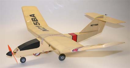
(1) POLY-T (is a construction article in the November 2006 RC MICRO WORLD online magazine [www.cloud9rc.com]). It is 110 square inches and weighs only 4.6 ounces with a Bob Selman Mighty Midget Gold Series 13/4/15T brushless outrunner (weighs 7 grams) and two 300-mAh Li-Poly batteries. The plane was designed to resemble a small commuter liner.
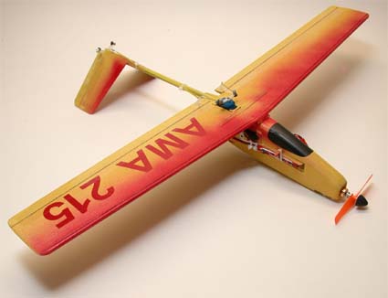
(2) EAGLET-II (will be in the January 2007 RC MICRO WORLD). It is 75 square inches and weighs 5.4 ounces with a Feigao brushless inner runner running a GWS 3x3 pro direct on two 340 mAh Li-Poly cells. This little plane features a flat 3/16 balsa wing (no airfoil) with a hardwood dowel leading edge. The tail boom is a Sports Authority carbon fiber arrow shaft. The inverted "V" tail is just to be different.
What is nice about these little planes is that they can be cranked out in a matter of days and are very inexpensive. This type aircraft could give ARF/RTF models a run for their money.
Return to "What's In This Issue"
More Motor Standoff Info
From Walt Thyng wthyng@earthlink.net
Another great Ampeer (Sept. 2006). Noted your comment on "stand offs" from the local hardware store. I recently acquired a MegaMax for my Nosen Citabria. I made up a standoff mount from nylon spacers available from my local ACE hardware. My mount is 3 1/2 inches per leg, so I used four one inch and one 1/2 inch spacers per leg with 10/32 bolts.
They have stood up very well to the power of the MegaMax on 34 cells swinging a 16x10 prop. I did learn one thing, however: they come in both thin wall and thick wall versions. I think the thick wall are better for our purposes as they provide a larger contact surface and should add stability. I need to make a small thrust adjustment and I will send photos when I do.
In order to accommodate the thrust adjustment I will have to use 10/32 threaded rod instead of bolts, as they don't offer 4 inch bolts at my local hardware store.
Walt
Return to "What's In This Issue"
MM_Calc AXI
From Louis Fourdan fourdanlouis@yahoo.fr
Dear Ken,
Maybe you remember January 2006 when you spoke a word about AXI_Calc (freeware). Now the name is MM_Calc (as there are also Inrunners from Model Motors) AXI is a code for only Outrunners. Now the complete line is up-dated.
You will find here electrofly.free.fr
Top icon "telechargements" then chapter "moteurs"
The site is in French but my software is in English (bad? from a French !)
I invite you to take and try it if you have some time.
I have also 2 databases (Outrunners and Inrunners) and 2 Diaporama (in french+pictures) for Brushless and Lipo batteries
Regards
Louis
Return to "What's In This Issue"
Letter from Ottawa on Good Service & Li Po Specs
From Rod Woolley rwoolley@sympatico.ca
Hi Ken,
It's so refreshing when you get good old-fashioned service especially when the same business strives to provide value for money!
Recently I ordered some NiMH cells from cheapbatterypacks.com. I wasn't sure what to expect. I had not used their services before, but their prices seemed reasonable, and they operate a good web site at www.cheapbatterypacks.com . They specialise in loose cells and custom made packs. I especially like the way they provide graphs for all of their cells and compare each cell with its principle competitors. I needed some sub-C cells for a 16-cell pack to use with an Astro 25G, and selected the Elite batteries 3600mAh cell, which is labeled EV118. I also needed a large number of cells to make up several 8 cell packs for Speed 400 models, and selected the CDP 1150, which according to their graph has a better output voltage and higher capacity than the KAN 1050 at 10, 15 or even 20A. This suggests to me that this cell will provide plenty of 'poke and umph' because it has a low internal resistance. Best of all it only cost $1.25!
'Cheap batterypacks' did everything right. They acknowledged the order via email and dispatched the order promptly. They ship via USPS rather than say UPS (who I hate with a vengeance because they inflict heavy broker fees and duties on shipments to Canada). It takes a bit longer via US mail but is less expensive and usually arrives in about 10 days I find. The shipping and handling costs were, I feel, kept to a minimum.
When I started to assemble packs I did a quick check of output voltage (one must not load a new cell before it has been slow charged but it's OK to use a digital voltmeter). I found that one of the sub-C cells was down at 0V whilst all of the others were well above 1V. I tried slow charging the suspected defective cell and it stubbornly refused to go up in voltage.
An email to Mike at Cheapbatterypacks.com immediately resulted in the re-assurance that he would ship a replacement cell. No quibbles and no need to waste time and money shipping the old cell back. A few days later and the cell arrived at no charge!
I have been so impressed with the service I would not hesitate to recommend this company to other folks.
Oh and one thing I forgot to mention... in the past I have become accustomed to making masking tape 'washers' to go over the positive terminal to prevent shorts due to solder splatters. I don't know how common it is nowadays, but neither type of cell that I bought needs this. An insulating washer is part of the construction and this saves time and effort when you are making a pack.
Whilst on the subject of batteries for propulsion packs, take heed of the following if you haven't realised already. When a manufacturer claims say 20C continuous dissipation for his Li-Po cells, try to check what the corresponding lifetime rating is if you do maintain that level of discharge. (Lifetime is the number of charge/discharge cycles before the pack drops to 80% of its as-new capacity). You may get a surprise at how few cycles the pack can tolerate. We should encourage distributors to publish this information for the cells and packs so that we can do a valid comparison. 'Flight Power' is to be commended for being open and honest in this regard. It would be nice if other manufacturers could follow suit.
Rod Woolley (OREO, Ottawa)
Return to "What's In This Issue"
Some Big Planes
From Hank Wildman hankwildman@comcast.net
EFO member, Hank Wildman sent along this photo of some of his "big'uns".
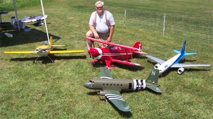
Here is a picture of my B777 and 1/3-scale, 16 lb. Pitts and also the 72 in. Polk C-47, Hank
Return to "What's In This Issue"
Mathematical Motor Modeling, Again
By Ken Myers
For many of us in electric flight, trying to predict how a new, unknown power system (motor/battery/prop) will behave has become a major pursuit. I have published many, many articles on this topic myself. Over the years I have followed the thinking and writing of many experts in this area. Countless numbers of power system calculation formulas, spreadsheets and computer programs have been written and much of the work goes back directly to Bob Boucher's published work with brushed DC motors (Electric Motor Handbook). While there are many variables involved in trying to predict the performance of any given motor, The Big Three were Kv (rpm/v), Io (no load amps to account for the amp "loss") and Rm (apparent motor resistance to account for the voltage "drop"). The ESC for a brushed motor system was handled, basically, as just another resistance loss in the total power system.
Brushless motors have brought many new variables into the process. With the commutation of a brushless motor being handled electronically by the ESC, the brushless ESC really needs to be considered a part of the motor.
Bob Boucher's Electric Motor Handbook describes the methods to collect The Big Three and how to use that information to predict how a given motor will perform with a certain load (prop in many cases) and applied voltage (number of cells). Unfortunately, The Big Three are not all that good at predicting the resulting RPM and amp draw.
Computer motor modeling programs using formulas that rely on The Big Three for the prediction of brushless motor performance are inherently flawed.
1.) Io does change with the voltage and the timing.
BP Hobbies BP 3520-6 & Jeti Spin 44-amp ESC:
Average Io (24-degrees): 16.0v, 3.57 amps; 19.3v, 3.92 amps
Average Io (0-degrees): 16.3v, 2.94 amps; 20v, 3.48 amps
In the brushed model Io (no load amps) is subtracted from Iin (Amps in) to account for Hysteresis loss, rotational speed loss, friction loss, and incorrect timing loss. According to Bob Boucher, "For the purposes or calculating motor performance one can assume that there is a leakage current or loss current shunting the ideal motor by an amount equal to the measured no load current or Io. The net effective current and the torque it produces are decreased to the values: Inet = Iin - Io".
Since some of these losses do not appear in a brushless design, and new losses, especially in the ESC, are introduced, Io does not appear to be a particularly good value to be used in a brushless motor modeling formula or computer modeling program. As I stated earlier, Io is more of a variable than a constant and if the motor timing of the brushless ESC is advanced from 0-degrees it becomes even more of a variable.
Here is some no load data from a recent motor test of mine.
Jeti Spin 44 0-degrees timing: 16.33v, 2.94 amps, 11808 RPM
Jeti Spin 44 24-degrees timing (Jeti outrunner default): 16.07v, 3.67 amps, 12360 RPM
Jeti Spin 44 0-degrees timing: 20.03v, 3.5 amps, 14520 RPM
Jeti Spin 44 24-degrees timing: 19.36v, 4.01 amps, 15000 RPM
2.) Rm cannot be relatively easily "measured" for a brushless motor/ESC combination.
Rm tries to account for a voltage drop due to the electrical resistance of the windings. The calculation of the voltage drop tries to create the Vnet (net volts). Vnet = Vin - (Iin * Rm).
Watts out = Vnet * Inet, but in a formula or computer model, this is true only if Vnet and Inet are accurately modeled. Using Io and Rm doesn't produce a very accurate model for brushless motors and their ESC companions and, as previously noted, Kv is dependent on timing.
3.) Kv changes with the timing.
Bob Boucher, Chapter 2, Electric Motor Handbook, "For this measurement (Kv) you need to make sure that that your motor is adjusted for neutral timing." Of course he was talking about a brushed motor, but it also applies to brushless motors as well.
Changing the motor timing changes everything.
It's a Matter of Timing:
While collecting the motor/ESC/prop data for my latest plane/power system, I asked myself, "How is the timing affecting the recorded data?"
As usual, I am working on a new plane and power system setup. While checking out the power system, I had "accidentally" gathered some no load data with the timing set at 0-degrees. I then set the timing of the Jeti Spin 44 to Jeti Model's recommended 24-degrees for outrunner type motors and gathered numbers that were different from the 0-degree timed data.
After running the battery/prop tests with the Jeti Spin 44 timing set at 24-degrees, I became curious as to what would happen if I set the timing to 0-degrees and repeated the battery prop tests. There were three factors that prompted me to do this.
First, I wanted to use a 5-cell Emoli battery in my latest project but found the 39 amp draw using an APC 10x7E with a True RC 5S1P 4000mAh Li-Po battery (doubling for the 5S1P Emoli pack I don't have) troubling. I have read and seen graphs that indicate that the Milwaukee V28/Emoli cells really drop voltage quickly after passing through the low 30-amp range and are good only to about 40 amps.
Second, my data did NOT come out anywhere near the data on the BP Hobbies' Web page for this motor. The BP Hobbies Web page shows, "APC 10x7 Sport, 19.2V, 35.6A, 684W, 12000 RPM". I had entered my collected data for the 24-degree timing tests into the Drive Calculator computer program (FREE @ www.drivecalc.de). The Drive Calculator program then gave me back information that was very, very close to my measured data, so I was pretty sure it was working well. I then entered the 19.2V and the APC 10x7 Sport prop from the BP Hobbies site information, set the elevation to 21m (Piscataway, NJ elevation) and the temperature as 20-degrees C as the inputs for Drive Calculator. The program came up with "42.7 amps, 819.8 watts in, 12758 RPM". That was too far off for my liking. I wondered why?
Third, I was just plain curious about the effects of timing!
I collected no load and loaded data with the ESC timing set to 0-degrees. I created a new motor in Drive Calculator using the 0-degree timing data. Once I had the new, 0-degree timing motor in Drive Calculator working well with my collected data, I used the BP Hobbies data noted above and Drive Calculator output, "37.4 amps, 718.5 watts in, 12277 RPM".
The numbers for the 0-degree timing are not what I call extremely close to BP Hobbies' published numbers, but they are a lot closer than when the Spin 44 ESC timing was set to 24-degrees. There are a lot of explanations for the differences between the Drive Calculator estimates and the published BP Hobbies' numbers, but I believe that the main difference is that the folks at BP Hobbies may have used a cheap, less-efficient Chinese ESC, which had greater losses in the ESC and thus the lower measured numbers. BP Hobbies do not state what ESC was used to gather the numbers or what the timing was set to.
It can be seen that timing plays an important part with how the motor performs both in the real world and in computer simulations.
I collected the following data by charging a Skyshark 4S1P 4000mAh Li-Po pack and then running a motor/battery/prop test using the APC 10x7E with the ESC timing set to 24-degrees and then 0-degrees. Before running the test, I "warmed up" the motor, ESC and battery by running two 10-second full throttle runs. The 24-degree test data was gathered first because it would draw the most amps. The ESC was quickly changed to 0-degrees timing, using the Jeti Spin Box, and then the second set of data was gathered.
24-degrees: 13.75v, 25.51 amps, 9390 RPM, 351 Watts In
0-degrees: 14.16v, 24.04 amps, 9330 RPM, 340 Watts In
While there appears to be an insignificant difference between the 0-degree timing and 24-degree timing on the 4S pack, when a True RC 5S1P 4000mAh Li-Po battery was used, the following data was gathered.
24-degrees: 17.10v, 39.03 amps, 11340 RPM, 667 Watts In
0-degrees: 17.47v, 35.86 amps, 11130 RPM, 626 Watts In
Again the difference is not huge, but it does make a difference when I'm planning on using the Emoli cells. The Emoli cells will be much happier with the maximum amp draw near 36 rather than near 39. By using the 0-degree timing I am giving up ~200 RPM while reducing the maximum amp draw by about 3 amps.
Previously I made statements about how accurately the Drive Calculator computer program predicts the performance of the power system I am using when the data is entered properly. Here is the proof.
Motor: BP Hobbies BP 3520-6
Altitude: 286m
Ambient Temperature: 20-degrees C
Jeti Spin 44 ESC timing 24-degrees
Prop: APC 10x7E
Measured using Emeter: 13.5v, 24.25 amps, 9174 RPM, Watts In 327
Prop: APC 10x7E (not the one supplied with the program but one I had recalculated to match my actual prop)
Drive Calculator output: 13.5v, 24.8 amps, 9236 RPM, Watts In 334.8
Jeti Spin 44 ESC timing 0-degrees, props same as above
Measured using Emeter: 14.0v, 23.55 amps, 9264 RPM, Watts In 330
Drive Calculator output: 14.0v, 23.0 amps, 9276 RPM, Watts In 321.4
It should be remembered that the real world "motor" was modeled twice for this program. A set of data was collected with the timing set at 24-degrees. That data was saved as the BP 3520-6 ESC timing 24-degrees. Then a second set of data was collected with the ESC set to 0-degrees. That data was saved as BP 3520-6 ESC timing 0-degrees. The outputs above are taken from the "two" different motors (meaning the ESC timing was different), thus illustrating the difference timing makes on "power system" predicting.
Conclusion:
According to Bob Boucher, advanced timing was used with brushed motors for "Sparkless Commutation". Motor sparking doesn't happen with a brushless motor, as there are no brushes. I have only been able to find vague references as to what timing to use with brushless outrunners and no explanation as to why.
Jeti Model Spin Box Instructions: "Motor timing (pre-ignition) -
Recommended values: 2pole motor...0-50, 4p motor...0-100, 6p motor..0-200, 8p and
more...20-300 - necessary in case of the so called reversed motor conception"
Castle Creations Phoenix Line of Controllers:
9.5 Programming Setting 5 - Electronic timing advance
Option 1: High advance timing (120-350) Recommended for higher pole count motors (eg. Jeti or large Mega motors) Gives more power at the expense of efficiency
Option 2: Standard advance timing (50-200) * Recommended for most motors (Aveox, Hacker, Astro, smaller Mega, Kontronik) Gives a good balance of power and efficiency
Option 3: Low advance timing (00-150) Recommended for use when efficiency or run-time is primary concern - Gives a slight loss of power with a slight increase in efficiency.
NOTE: The controller senses the motor type by its inductance, and automatically sets the maximum advance according to motor type (eg: outrunner motors will automatically be run at a higher advance setting)
I guess I am still uncertain as to why the recommendation for outrunner brushless motors seems to be to set the timing at 20-degrees or more. I am looking for the answer as to why this is the recommendation? Also, what is "wrong" with running a brushless outrunner at 0-degrees timing for higher efficiency?
Return to "What's In This Issue"
Happy Holidays to ALL and have a Wonderful New Year!
Return to "What's In This Issue"
|

