 |
Flying High With Electric Power!
The Ampeer ON-LINE!
December 1998
The Club Newsletter of the Electric Flyers Only, Inc
AMA Charter 2354
Walled Lake, MI, USA
Editor: Ken Myers
Fly the Future - Fly Electric!
|
What's On This Site:
Site Table of Contents
| President: | Vice-President: | Secretary/Treasurer: |
| Ken Myers | Richard Utkan | Debbie McNeely |
| 1911 Bradshaw Ct. | 240 Cabinet | 4733 Crows Nest Ct. |
| Walled Lake, MI 48390 | Milford, MI 48381 | Brighton, MI 48116 |
| (248) 669-8124 | (248) 685-1705 | (810) 220-2297 |
 |
| Board of Directors: | Board of Directors: | Ampeer Editor |
| Jim McNeely | Jeff Hauser | Ken Myers |
| 4733 Crows Nest Ct. | 18200 Rosetta | 1911 Bradshaw Ct. |
| Brighton, MI 48116 | Eastpointe, MI 48021 | Walled Lake, MI 48390 |
| (810) 220-2297 | (810) 772-2499 | (248) 669-8124 |
| Mailed Ampeer subscriptions are $10 a year US & Canada and $17 a year world wide.
FREE on-line! |
| The Next Meeting:
Date: Saturday, December 12, 1999 7ish - McNeely residence (see map) |
The November Meeting
The November meeting was highlighted by a lot of plane talk. Ken noted that the timing of
the AF 90 would take place in January and include timing of all motors from Speed 400 up.
Several of the members had some very nice planes to share with us.
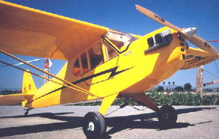
Doug Kursinsky had a Hanger 9 Cub. It is powered by a direct drive AF 60 that
uses a 15x10 prop and 28 1500mAh cells. It weighs in at 12 pounds. He felt that it a lot of plane for the money, but he did have
several problems. The wings had to be replaced. The tail feathers were warped, and the landing gear is not strong enough. He
felt that the first flight went very well, and there was plenty of power.
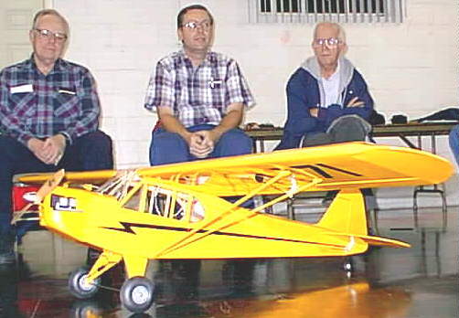
Jack Lemon on left, Doug Kursinsky center, Ernie LaBelle right.
(Use back button to return after opening thumbnail.)
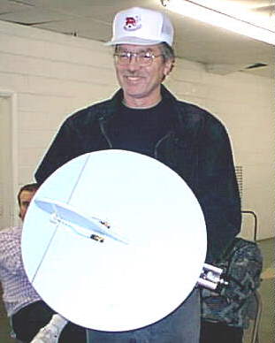
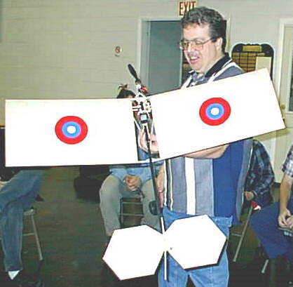
Richard Utkan had a flying circle for Speed 400 that he’d scaled down from a
glow powered version. We were all intrigued and can’t wait to see it fly - or not! Let us know Richard. He also had a free
flight ducted fan called the Sonic Blast. He says that it flies nicely and is a lot of fun.
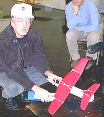
Mike Holroyde had the Blue Foamie that he had flown at the October meeting. It
had an interesting 6x4 yellow prop on it, that he said he’d gotten from Kirk at
New Creations R/C. He also had a slo-fly Demoiselle. He’d not flown it yet,
but said that the instructions were so bad he had to use an ad to see how the plane was put together. It is cute though and should
fly well.
Speaking of things Hobby Lobby, the Wingo has been receiving some nice comments on the
Ezone Magazine’s eflight list.
Ken brought up the black wire syndrome again. Folks, be sure to check for this airplane
killer. It will happen to the black wire in your Tx, Rx and your power batteries. It is very dangerous. Just strip back some of the
insulation on the black wire. If it is not shiny wire, replace it IMMEDIATELY!
See you all at Debbie and Jim’s for the December meeting/party.
Return to "What's In This Issue?"
DSC - Direct Servo Connection for CL models
By: Fred Cronenwett email: clscale@gateway.net
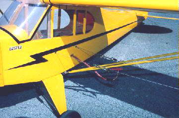
The size of the painted 16-8 is very clear here. Yes, it's a control line electric!
Control Line models being flown today are a far cry from the models flown in the 50’s and 60’s. They are larger, lighter and have more features. The modern CL model can take advantage of commercially available retractable landing gear, fiberglass fuselages and electric motors. In the past if you wanted retractable gear on a CL model you would have to install a 4th line and all of the required pushrods to make the system work. These mechanical systems are difficult to set up. What if I told you that you could purchase a JR radio system, retracts and a model airplane kit and use all of this for a CL model without any special modifications other than the bellcrank?
Basically, the electronic CL model uses a normal 2-line bellcrank and handle to control the elevator. The lines are insulated and are used to carry a signal and ground from the transmitter to the receiver. The insulation keeps the lines from shorting out. These systems take advantage of existing Radio Control technology and use it where is was never intended to be used. The electronic CL model flies with two lines and can operate up to 8 independent functions all controlled by individual servos. The traditional CL scale model would have used a 3-line bellcrank with additional lines to operate other features.
The next time you are in the local Hobby Shop take a good look at the JR XP642 radio. On the back of the transmitter there is a jack with the letters DSC next to it. DSC stands for DIRECT SERVO CONNECTION. When you start digging through the instruction manual you find that the DSC function is designed for the R/C pilot to be used in the pit area. It allows the pilot to check the operation of the functions without transmitting any kind of radio signal. The DSC function basically hardwires the transmitter to the receiver bypassing the RF decks. This article will show how the DSC function can be used on a CL model and how it’s advanced features makes this radio a real plus. This radio can be used for a CL model without any special conversion required.
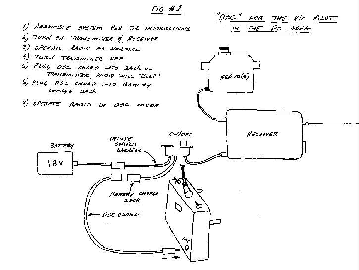
Figure 1: Click to view image, back button to return.
Figure #1 shows how the radio is set up to be used in DSC mode for RC use in the pit area. One special note, the normal switch harness that comes with the XP642 radio needs to be replaced with the deluxe switch harness that has three wires for each bundle. The DSC function will not work with the normal switch harness that comes with the XP642 radio. The DSC chord also needs to be purchased, it is about 6 feet long it plugs into the back of the transmitter and the charge jack on the receiver switch harness. If the Transmitter is turned ON with the ON / OFF switch on the front of the Transmitter then you will be transmitting a radio signal, to turn on the transmitter for DSC mode just simply plug the DSC chord into the back of the transmitter, you will notice the transmitter turns ON, yet the ON / OFF switch is still in the OFF position. Turn on the receiver as you would normally.
You will notice the radio works the same as if you where transmitting a radio signal. The XP642 is a 6 channel radio with four spring-loaded sticks for normal elevator, rudder, aileron and throttle control operation (If used for R/C operation). Two additional toggles can be used to operate two other functions such as flaps and retracts. The radio has some other features such as 4 model memory, end point adjustment and servo reversing. We have been flying with these JR radios for the last year now and use the end point adjustment and the multi-model memory the most.
One of the models that I fly with the DSC system is a Sig Kadet Seniorita. I built the kit per Sig’s instructions, except I made the airplane into a tail dragger, added flaps and changed the nose section. I have a total of six (6) servos in this model. I have one servo each for the throttle, rudder, elevator and camera shutter release. In the wing there are two servos, one for each flap. By now you are wondering why in the world I installed a servo for the elevator and rudder on a CL model - I will get to that later. I also added the Ace Servo Master between the receiver and the flap servos.
The Ace Servo Master was installed to slow down the deployment of the flaps. I have the flaps on a toggle switch, and normally any toggled servo will move very quickly, dropping the flaps in less than one second. When the flaps are deployed the nose tends to pitch up and changes the trim of the model. By using the Servo Master, I was able to slow down the deployment of the flaps to five seconds. This allows the pilot to change the elevator trim as the flaps come down. It looks more natural and adds to the realism if flown in CL Scale competition. The Servo Master can also be used to sequence landing gear doors. One servo would be used to open and close the doors, while another servo is used to operate the air valve. Only using one channel, both servos are sequenced by the Servo Master.
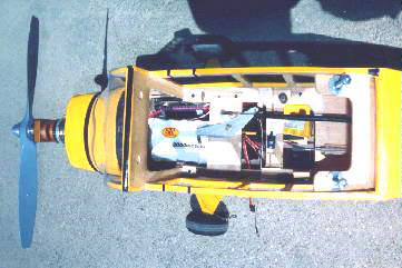
Shot showing CL bellcrank, battery and JR receiver
Remember when we had the radio working in DSC mode on the workbench and we had the DSC chord plugged into the Transmitter and the switch harness? Now all we need to add is a set of flying lines between the DSC chord and the switch harness to make this setup complete. The flying lines must perform two functions. First the lines are structural members that must withstand the rigors of pull testing and operate the bellcrank for the elevator control. I will explain the elevator servo later. The lines must also transmit the electronic signal and ground from the DSC chord to the receiver switch harness. Basically we are extending the 6-foot long DSC chord to 70 feet with the flying lines.
Typical setup for flying lines hooking up to plane with DSC wire connection |
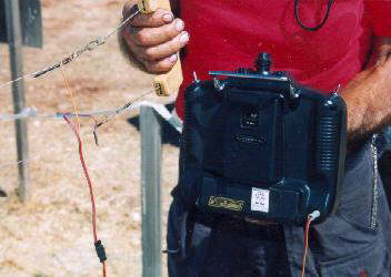
This shows how the DSC cord plugs into the back of the transmitter and into the lines. Transmitter hangs
off of pilots belt.
|
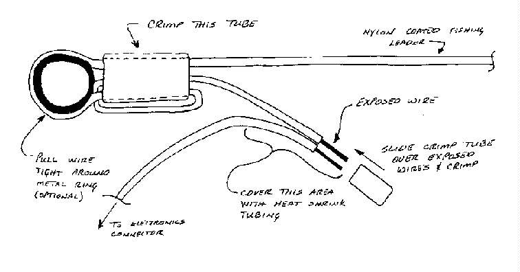
Figure 2: Flying Line Construction
The actual lines themselves are nylon coated salt water
fishing leader. The 7 stranded steel lines are the same identical lines normally used for CL
models except the lines are nylon coated to prevent the lines from shorting out when they
touch. The fishing leader can be custom ordered from your local fishing store. Remember to
measure the actual wire diameter without the nylon coating. Select the wire diameter based
upon the following table. Assemble the lines as described in figure #2. Refer to figure #3 to
see how the entire system works as a whole.
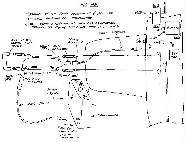
Figure 3: Whole System | 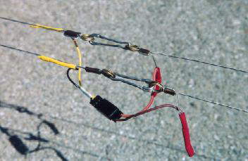
This is the typical connection between the handle and lines, or airplane and lines. The DSC connector and wires can be clearly
seen |
| Model weight | Min Line Diameter |
| 0-4 lbs. | .015 |
4-8 lbs. | .021 |
8-20 lbs. | .027 |
Why bother with this system when you are happy with the 3-line handle that you have been using for many years. Ask yourself these questions - how many features can it operate? Does the 3-line handle allow the neutral elevator adjustment to be made easily? If you wanted to add flaps, retracts and bomb drop are you prepared to add 3 more lines to the model? The drag from six flying lines is rather substantial. The electronic control system can operate all of these functions with only two flying lines.
Electronic controls allows the user to eliminate all of the pushrods, springs and other mechanical connections required for 3-line systems. You can locate all of the servos right next to the mechanical device such as the flaps or air valve. All you have to do is install a short pushrod and you are done. But this computer radio has two features that makes setting up a CL model in DSC mode extremely easy, servo reversing and end point adjustment. While servo reversing is nothing new, this feature is standard on this radio. This allows the direction of the servo arm rotation to be flipped, allowing any orientation for installation inside the airframe.
End point adjustment changes the amount of travel of the servo arm. This comes in handy when hooking a servo up to an air valve or flaps. Often times you have to use a really short servo arm to reduce the amount of throw for flaps. Normally a toggled servo will result in about 160 degrees of throw. With servo end point adjustment you can limit the amount of throw from 0% to 150%. One special note, when I tested a retract servo with end point adjustment it did not respond to the end point modification. The servo always rotated the same amount regardless of the end point adjustment.
When I set up the flaps on the Seniorita I used end point adjustment to line up the trailing edge of the flap with the trailing edge of the wing. I used the other end point to adjust how much flap is deployed. Changes can be made at the field in a matter of minutes. This way you can use a normal servo arm and never adjust the clevis hooked up to the flaps. This can be used on all of the other channels resulting in the exact amount of throw required for the job (except for retract servos of course).
Since this radio has four model memory, you can store up to four different settings for each channel, including end point adjustment and servo reversing. You can have one transmitter and purchase additional receivers, switch harnesses, battery and servos for each additional model. Other JR radios have even more model memory if four does not suit your needs.
I started flying with Grant Hiestand in 1989 and he started to really investigate the possibility of flying with electric power and throttle control. Since electric power is a purely electronic device there is no mechanical 3-line system that can control for this type of power system. When we first started using these electronic systems he discovered that CL electronics and electric power was a perfect match. Electric power is the perfect power source for aircraft with lots of wing area. Grant has a whole fleet of electric powered CL models all with throttle control.
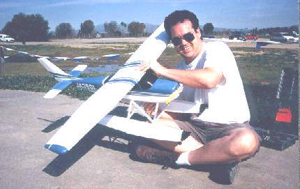
Grant Hiestand with his Sureflight Cessna, 015 powered geared electric powered (normal gearbox). |
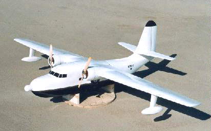
Grant Hiestand’s G&P Sales Albatross converted to Twin powered Electric with Astro 25’s
|
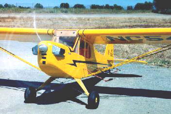
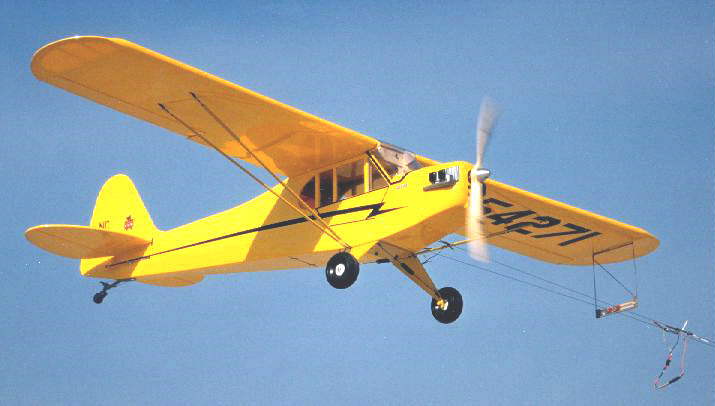
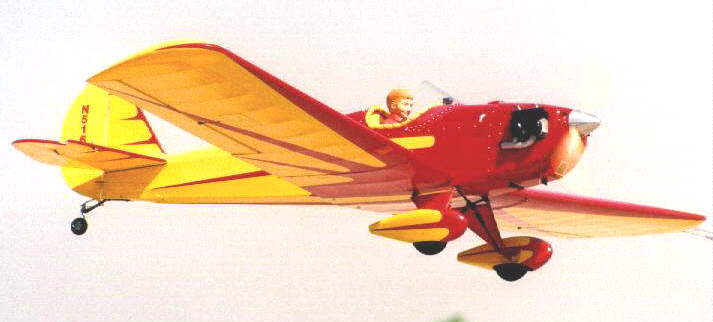
I recently put together a Hanger Nine Piper Cub and now fly this model with an Astro Geared 40 motor and 21 cells (2000 Max). Even with 2+ lbs. of batteries this 9 lb. model flies great for over 10 minutes on one charge. Swinging a 16x8 inch propeller the Astro 40 with the Super Gear Box is perfect for scale models. The huge propeller generates lots of thrust and flies at a scale like speed. This model was flown at the 1998 Northwest Control Line Regionals in Roseburg, Oregon. It was flown off the new ROW pond. Even with floats, and weighing in at 11 lbs., it performed without any problems. The speed control replaces the servo normally used for throttle and plugs directly into the receiver. For more information on electric power there are a number of books on this subject.
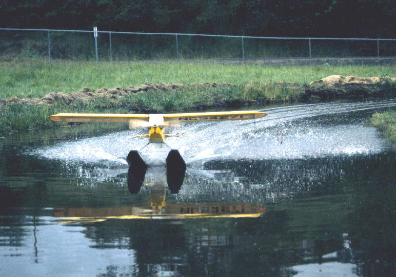
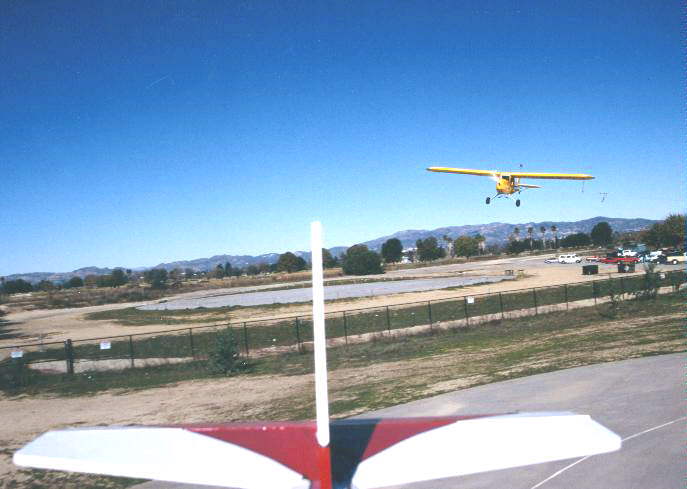
Fred Cronenwett’s Hanger Nine Cub coming in for a landing at the NW Regionals Control Line ROW pond. Flying with Great Planes 60 size floats, Super box geared 40, 18-10 prop, 21 cells, 2000 mAh.
Earlier I promised that I would explain why I installed an elevator and rudder servo in this model. Remember that the only difference between operating this radio in DSC mode and normal R/C mode is that we plugged in the DSC chord between the airplane and transmitter. We have the same transmitter and receiver and they still have the crystal installed. If we left the flying lines at home, moved the elevator pushrod to the elevator servo, removed the wing tip weight and line guide this model can be flown R/C style. Then with another 5 minute conversion it can be a CL model again. All of this is can be done using the same receiver and transmitter.
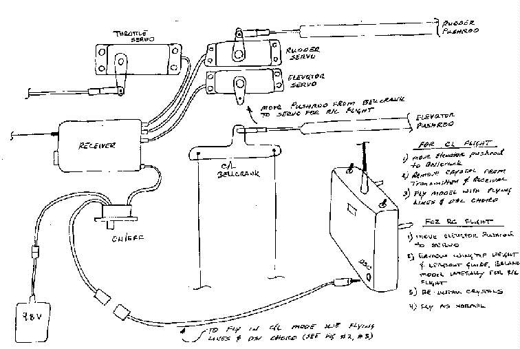
Figure 4
This Seniorita has already been flown as a R/C model using the same transmitter and receiver that I use for Control Line flying. The only difference between a R/C model and CL model is that the elevator is controlled by a bellcrank for CL flight.
Refer to figure #4 to see how the Seniorita was set up. During CL flight the rudder is not used, while the flaps and throttle are used throughout the entire flight. This allows us to build one model and fly it in either mode, CL or R/C with a very quick conversion time.
I ran another test that you must keep in mind when you go to your local flying field. The CL site that I fly at is very close to a R/C flying site so if I left the crystal in the receiver, turned the airplane on without the DSC jack plugged in, my plane will pick up a signal from a nearby transmitter on the same frequency. If the DSC cord is plugged into the model a nearby transmitter on the same channel will not affect the airplane, but when you unplug the DSC chord watch out. To be on the safe side I leave the transmitter and receiver crystal at home so that there will not be any problems. If you assemble your plane to be flown as a R/C and CL model using this system make sure you can easily get to your receiver to remove or install the crystal quickly.
When flown as a CL model the transmitter is attached to the pilot’s belt and is operated all by touch. A few minutes of practice is all that is required to get use to the setup. The DSC chord, that is available from JR, is the perfect length to go from the transmitter to the handle during flight. JR also makes other radios such as the F400 (4 channel) and the ultimate XP8103 eight channel radio. The 8 channel radio has increased model memory (8 model memory) and still has the DSC function. Even the F400 has the DSC function however the instruction manual does not show you how to use this feature. To date we have flown CL models with the F400, XF622, XP642 and the XP8103. Any JR radio with a DSC jack on the back of the transmitter can be used for CL flying without any special modification. Remember that you need the DELUXE SWITCH HARNESS and the DSC CHORD to make the system work properly. The XP8103 automatically comes with the deluxe switch harness while the XP642 and F400 do not.
We have been flying with electronic controls in our Scale, Carrier and Sport CL models since 1990 with three different systems to date. The simplest is called SINGLE CHANNEL and it can only operate one function. It uses a servo driver that is mounted to the pilot’s belt, the model has a 6 volt battery and a servo. The SINGLE CHANNEL model still only uses two flying lines. Single channel should not be used with electric powered systems, the modern speed controls and single channel do not get along! We have also flown with converted R/C radios with great success. These systems are called MULTI CHANNEL CL ELECTRONICS, however the radio has to be permanently modified which adds additional cost and time to get up and running. The JR radios do not have to be modified since they can be used for R/C or CL use direct from the factory.
These types of control systems for CL models have been in use for many years and have a proven track record. The entire 1998 FAI CL scale team flies with multi-channel electronic controls. Grant, many others, and myself have flown hundreds of flights with these systems in Carrier and Scale competition. The transition from 3-line to electronics requires a new set of rules and offers many rewards. I have talked with many CL pilots who first thought they would not like the transmitter hanging off the belt. After trying the system with one of our models, we found they never built a 3-line model again. Good luck and enjoy!
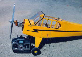
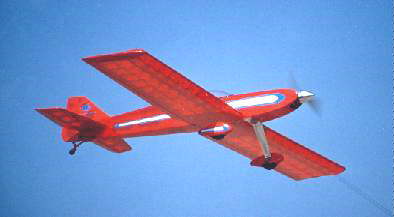
No glow plug or other ugly holes. I love it when someone walks up the plane, spots the 16-8 prop and can’t find that great big gas motor, no muffler or other sign of power. I let them squirm for 5 or 10 minutes then tell them it’s electric!
The Spacewalker is powered with an Astro 90 geared motor and weighs 18 lbs.
total. The model was built by Grant Hiestand. He took first place in Precision scale at the 1993 Nationals for Control Line. This
model uses DSC electronic controls
The Piper Cub, mentioned throughout the article is the plane I fly with a 16-8 prop,
Geared 40 super box, 21 cells, 2000 mAh and DSC electronics. The plane has been flown at 9 to 13 lbs. total weight. The plane
can carry a 8mm video camera. This model has also flown from an Control Line ROW pond (with 18-10 prop). It is a Hanger
Nine ARF kit with modifications. A great first project for electric power. This is the first electric powered model for me.
The other photo was taken from a Sig Seniorita carrying a Canon 35mm camera
(2lbs. of camera). The plane was powered with an OS-40 FP (gas motor, sorry) and the camera was tripped with a servo.
Model was flown with DSC electronics.
Return to "What's In This Issue?"
News and Deals from Modelair-Tech
P.O. Box 1467, Lake Grove, N.Y. 11755-0867
Phone and Fax: 516-981-0372
E-Mail: modelairtech@rc-aero.com
Modelair-Tech Post KRC/Fall Specials
For those of you who could not make it to KRC this year, here are some specials run at the show.
- GD-100 or GD-101 ... $20.00 or two for $38.00 (reg $24.95 each)
- GB-100 only ... $13.95 (reg $15.95)
- $2.00 off all plans $19.00 or less
- $4.00 off all plans $20.00 or more
- $5.00 off all "Stik" kits (reg $25.00)
- $2.00 off W-107 Nose block (for Soarwatt, Wingwatt, Bare Bones, Meagerwatt plans) (reg $5.00)
LP146 Slowmowatt
- an Indoor/outdoor "slow flyer"
- for the GearDrive 280 motor/gearbox combo
- Wing area: 430 sq.in.
- Wing span: 51"
- 7 cell 150-350 mAh pack
- Weight: 10-12 oz.
- 13-14 minute flights possible on 350's!!!
- Built mostly from sticks and scrap sheet wood.
- Build flat bottomed or undercambered wing airfoil.
- Very easy to build and fly!!
 |
PCOMBO-001
The Slowmowatt is also available as a "combo" with the GearDrive 280 and
Doculam covering material (COV-001). Plans/combo-280/78" x 25" of Doculam.
By now most of you know that a neat little motor/gearbox /prop combo for Slow Flyers,
The GearDrive 280. |
I have a new motor/gearbox/prop combo for indoor and outdoor "slow flyers" I
am importing from Germany (Titanic Airlines) (GearDrive 280) as well as a new "stik" model plan offering.... the
Slowmowatt "slow flyer" for the above system. The Twin Dimwatt is now a Kit!!! Now, all "stik"
kits come complete with laser cut ply parts, so literally all one has to do to put one together is "chop sticks" (pun intended).
Coming....... for release before the WRAM show....
The Tumblewatt (speed 400 stik aerobat) Kit or plan
The Super Soarwatt (larger version of our Soarwatt for geared 400 motors) kit or plan. The
Boxathalon ( a stand way off scale Decathalon) stik model plan for the H-100 belt drive/sp400 or the MGB-50 sp400
motor/gearbox
Regards and thanks - Tom Hunt
Return to "What's In This Issue?"
Next Meeting: Saturday, December 12, 1998, 7:00ish at the McNeely's
See Map
Return to "What's In This Issue?"
Upcoming Events
Return to "What's In This Issue?"
To Reach Ken Myers, you can land mail to the address at the top of the page. My E-mail
address is:
KMyersEFO@aol.com EFO WEBsite: http://members.aol.com/KMyersEFO/