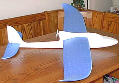
Multiplex EasyStar RTF (Ready to Fly)
A Review: By Ken Myers
The Multiplex EasyStar RTF is marketed as a buy it, fly it, ready to fly for beginners. In my quest for a good R/C trainer for the beginner, I ordered the Multiplex EasyStar from Northeast Sailplane on December 5, 2003. I had read a review of this plane by Jim Rayven in the December 2003 issue of Quiet Flyer, and it had piqued my interest.
The plane comes as a complete package including the airframe, radio, charger, power system and flight battery. I was curious as to whether it could live up to its aspirations of being an excellent trainer plane for a beginner for under $200, as many planes marketed in this category are not!
Jim's review was for the airframe and motor/prop combination only. He supplied his own R/C equipment, flight battery and charger. As with most articles, I felt it was short on some of the information that I wanted to know. It did not include some niceties like RPM and amp draw of the supplied motor and prop combination.
The amp draw number became important to me as I waited for my EasyStar to show up. I decided to put the motor constants (Kv = 3026, Io = 0.7 Rm = 0.357 Wt.=2.6 oz/73.7g via Motocalc data) for the Permax 400 6v (the supplied motor) into my spreadsheet to check the performance of the motor. The complete power setup, provided in the RTF version, also includes a Multiplex Pico X-08 ESC (electronic speed control) w/BEC (battery eliminator circuit). The ESC is rated by the supplier at 8 amps continuous and 11 amps maximum.
I didn't like the numbers that I saw when I ran my spreadsheet data. It seems that this motor is not very efficient, even for a low efficiency S400 type.
The supplier quotes the wing area as a questionable 390 sq.in./25.16 dm2, while Ray's review said 372 sq.in./24 dm2.
Supplier data: (on the Northeast Sailplane site)
Skill Level: BEG/BEG
Wingspan: 54 in.
Wing area: 390 sq in?
Weight: 24 oz.
Wing loading: 9 oz/ft?
Airfoil: undercambered
Motor: Speed 400
Battery: 7- 8 cell 500-1050 Nicad-NiMhd
Ray's review data:
Description: Park Flyer Motor Glider
Skill Level: Beginner
Wingspan: 54 in.
Wing area: 372 sq. in.
Weight: 22.5 oz.
Wing loading: 8.7 oz/ft
Motor: Speed 400 direct drive
Battery: 7-cell 600 mAh Nicad
Propeller: 5x4
Ray called it a Park Flyer, but at the end of his article he recanted by saying, "An athletic field, while suitable for typical park flyers, would generally be too small for this model."
I decided to see what "category" or "task" this plane matched in my database.
I have found that a "typical" direct drive motor glider has a weight factor of 1.2 to 1.3, prop diameter factor of 1.1 to 1.5 and pitch factor of 0.5 to 0.6. Using 24 oz. for the weight, 390 sq.in. for the wing area and a 5x4 prop, the EasyStar has a weight factor of 1.213, a diameter factor of 0.82 and pitch factor of 0.88. The weight factor is in the ballpark for a motor glider, but the small prop factors indicate that it could be faster than other planes in this category and have less thrust.
I checked my data for park flyers and backyard flyers and found that this plane didn't meet the criteria of either group. On paper, it was a "fast" flying motor glider type.
A week passed, and I received the EasyStar on December 11. As I handled the box, I heard a rattle. Something was loose inside. It turned out to be the transmitter antenna. There appeared to be no damage to the foam parts caused by the loose antenna.
When all of the contents were removed from the box, there was a little black piece of plastic lying on the bottom. The plastic piece turned out to be part of the canopy/hatch hold-down. It had broken off the canopy/hatch in shipping. I used baking soda and CA glue to "repair" the broken part. A beginner might not know how to have done that, but a piece of tape would have worked to hold the canopy/hatch onto the fuselage.
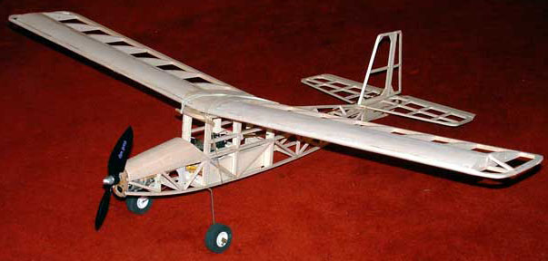
I was surprised, while reading through the instructions, that there was no mention made of how to assemble the wing and spar and affix the wing to the plane. I knew the spar, which had been taped to the top of the box, had to go into one wing panel, and then that wing panel was inserted into the fuselage. The other wing panel was slipped over the spar and then inserted into its slot in the fuselage. The plane now had a wing. The snug fit of the parts is intended to keep the wing in place.
Before I could affix the tail-feathers, which is the first step listed in the instructions, I had to use two pairs of pliers to straighten the rudder pushrod. The manual says to attach the tail-feathers using the supplied, and already in place, double-sided tape. This proved problematic, as removing the paper covering from the double-sided tape was not an easy task. A sharp, pointy kitchen knife did not work well. My solution was to use a single-edged razorblade to cut and lift a small portion of the protective paper that was covering the tape. Then I lifted the little "chunk" of paper pulling the rest of the protective covering with it.
I noticed that the elevator hinge felt very stiff, so I worked it back-and-forth several times before "sticking" the horizontal fin/elevator to the fuselage, using the wings as a guide to keep the tail aligned. The horizontal and vertical fins were attached with the elevator and rudder pushrod wires through the pushrod connectors, but the pushrod connectors were not tightened. They would be tightened later in the neutral position when the radio was turned on for the first time.
The Hitec Focus III SS 3-channel 72 MHz AM radio was loaded with 8 AA Duracell batteries, which I supplied. The trims on the radio were centered, the transmitter turned on, and the flight battery plugged into the speed control. The pushrod connectors were tightened with the surfaces on the plane and the trim levers on the radio in neutral positions. It was then that I noticed that no one had set the radio control throws up in the "standard" way for this plane. The elevator was reversed! It is not a big deal to flick the reversing switch on the transmitter, but a beginner wouldn't know this because nowhere in the instructions or radio manual is the "correct" movement mentioned. They could learn to fly in a "backwards" manner on the elevator stick. To the beginner it might seem "correct" to push the stick up to make the plane climb and pull it back to make it dive or go lower. Luckily, the rudder was correct, so the only problem would be when a self-taught beginner would have to relearn flying a plane with the elevator stick moving in the generally accepted direction. I know that you can learn to fly with the elevator stick moving in the "wrong" direction. Don't ask! It was 1962. I was a kid. I'd never been in a plane or cockpit.
Following the instructions, I had removed the battery for charging. Removing the battery was not easy, as access to the battery is not good, even for my small hands. I found the battery to be a 6-cell pack made up of Sanyo N-600AACL cells. It weighs 4.93 oz./140g with leads, connector and Velcro®. The specification for the Sanyo N600AACL cell is 0.74 oz./21g with an internal resistance of 0.0247.
This pack bothered me. First, Jim had used a 7-cell 600AE pack (from photo) and the Northeast Sailplane information said, "7- 8 cell 500-1050 Nicad-NiMhd." Would there be enough power from a 6-cell pack? Also, the 600AACL pack is about one ounce heavier than an equivalent 600AE pack. Since weight is critical to a good flying electric, this didn't make sense to me.
The supplied charger is labeled as a Hitec CG-72S. There are no directions with the charger, but the manual notes to charge the battery for 30 minutes. There is a 30-minute mechanical timer on the charger. The only other note is on the charger itself. It says, "7.2V-1200mA Quick Charger". With that information on the charger, it didn't seem correct to me to charge the 600-mAh capacity battery for 30 minutes. The other thing that bothered me was that the battery was in an unknown state of charge as received from the supplier. There was no mention of completely discharging the pack before charging it.
After depleting the charge in the shipped pack by running the motor to the ESC's voltage cutoff, I decided to hook up my digital voltmeter and do an "old-style", eyes on the voltmeter watching for the voltage drop, peak charge. As usual with this "old" type of peak charging, I became distracted. When I checked the voltmeter at the 20-minute mark, the meter was already steadily dropping. Thirty minutes would have been way too long, and could possibly have irreversibly damaged the battery.
With the battery charged, the plane was just about ready for its maiden flight. As I loaded the plane into the truck, I noticed that the receiver antenna was taped to the bottom of the fuselage for shipping. I pulled the receiver antenna free from the tape so that it could trail behind the aircraft. If I'd have left the antenna taped to the bottom of the fuselage, the range could have been shortened. There was no note in the instructions about freeing the antenna.
Just before I left for Clara Miller Park to test the plane, I checked the weather for Walled Lake on my computer. At 4:00 p.m. it was partly cloudy, 25 degrees F/-4 degrees C with a 14 mph/22.5 km-ph wind from the west. Not a great day for testing this type of plane.
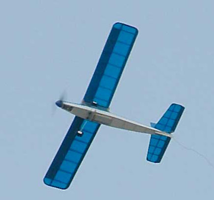
After completing a range check, I pointed the nose of the plane into the wind and gave it a gentle toss. It flew straight away, climbing like a rocket. With a few passes and a lot of down trim, it was flyable in the bouncy air. The wind continued to pick up and blew my hat off, but the plane remained controllable in the "bumpy" air. With the cold temperature, wind chill and high wind velocity, I did not fly out the pack! I elected to land after 5 or 6 minutes. Landing a very lightly loaded plane is interesting in this type of wind. It did not want to come down. Finally, I forced it down into a flat belly landing. No harm done.
While flying the plane, I noticed that the ESC has a very small control range with this transmitter setup. It doesn't come on until the transmitter throttle lever reaches about half of its travel. The range of RPM change does seem adequate though, as it goes from slow, level flight to a good climb rate. The rudder and elevator have a "slow" or "sluggish" feel about them. This is good for a beginner, as the surface movements proved more than adequate to handle the bumpy winds the plane was tested in.
At home, I ran out the pack. It continued providing power for about two or three minutes before the automatic voltage cutoff on the ESC kicked in.
I couldn't do further flight-testing until December 26 because of days of constantly high winds. The second flight on the plane went well in the 8 mph wind. Snow had fallen on December 25, but conditions were supposed to improve through the day. When I left for the park, conditions were; sunny, 23 degrees F/-5 degrees C, and winds from the WNW at 8 mph/13 km-ph. The flight went well with a smooth landing in the fresh fallen snow. The only problem was that the canopy/hatch hold-down had broken again, so the flight was made without the canopy/hatch.
I recharged the battery at home and fixed the canopy/hatch once again. Flight conditions for the third flight on the plane were; sunny, 24 degrees F/-4.5 degrees C with winds out of the west at 8 mph. This flight lasted over 11 minutes. The flight consisted of lazy circles in front of me with the throttle reduced the whole time except for the initial climb to altitude. The throttle was always on and never shut off until the low-voltage circuit of the ESC cut it off. Landing was easy and gentle in the new fallen snow. Even though the air was a bit "bumpy", the plane showed no bad flying characteristics and would "right" itself when I allowed it to.
After returning home with the depleted pack, I decided to check the charge time to peak using the battery in my truck. I'd been using my marine/RV battery in the basement, so I checked both the time and amount of amp input. The charger was putting out 2.5 amps at the beginning of the charge and 1.4 amps when the voltage peaked. That's an average of about 1.85 amps for the charge. The battery voltage peaked in about 20 minutes, as would be expected for the average charge rate and capacity (600 mAh) of the battery. I used my digital voltmeter to detect the peak using the "old" method of peak-detection - watch for it!
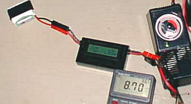
I had changed the supplied connector on the battery and Hitec CG-72S to APPs (Anderson Power Poles) so that I could put an Astro Flight Whattmeter inline during the charge. By changing to APPs from the supplied connectors, I lowered the circuit resistance some, so the figures that I got are slightly higher than what would be expected with the supplied "Tamiya-style" connectors.
As noted above, at the beginning of the charge, the charger was putting out 2.5 amps. Most people recommend a charge rate of 3C for Ni-Cads. That is three times the capacity. In this case, a 0.6 Ah battery times 3 would indicate a charge rate of 1.8 amps. I've charge almost all of my Sanyo Ni-Cads at 4C over the years. My charge rate could be 2.4 amps. The flight battery peaked in approximately 20 minutes. If a beginner were to charge the flight battery for thirty minutes, as the manual indicates, the flight battery could be quickly ruined.
I strongly recommend that the instructions for the charger be amended to read, "Be sure that the flight battery is completely discharged before charging. Set the timer for twenty minutes. Feel the battery with your hand as the charge continues. If the battery feels uncomfortably warm, even if the twenty minutes are not up, remove the battery from the charger. Never turn the timer to the off position."
No mention was made in the manual about not turning off the mechanical timer. It is a very good practice not to turn it to the off position. The timer should be left alone to just run out on its own, even if the battery needs to be taken from the circuit because it is charged. The instruction manual says the green LED will go out when the battery is charged. It doesn't. It goes out when the timer shuts off, which has nothing to do with the state of charge in the battery.
The Specifications on my particular example:
Weight RTF: 21.16 oz./600g (weighed on my digital scale - no decals)
Wing area: 372 sq.in./24 dm2 (going with what's in the manual - too hard to measure this odd shape. I tried.)
Wing loading: 8.19 oz./sq.ft.
Prop: Gunther 4.92"x4.33"/125mm x 110mm
Estimated Radio Weight: (radio came pre-installed so couldn't weigh the components)
Hitec HAS-03MB: 0.81 oz./23g (from HitecRCD site)
2 each Multiplex Tiny-S Micro Servos: 0.6 oz./17g ea. - 1.2 oz./34g (from Multiplex site)
Multiplex Pico X-08 ESC: 0.28 oz./8g
Fudge factor: 5%
Estimated airborne total component weight: 2.4 oz./68g
Airborne radio component weight Percent of RTF weight: 11%
Estimated Power System Weight:
Battery weight (w/Tamiya-style connector,leads & Velcro®): 4.93 oz./140g (weighed on my digital scale)
Permax 400 6v: 2.6 oz./73g (Motocalc data)
Fudge factor: 5%
Estimated Power System Weight: 7.9 oz./224g
Estimated Power System Weight Percent of RTF weight: 37%
Completed Airframe Weight estimate: 10.86 oz./308g
Weight Factor: 1.139
Prop Diameter Factor: 0.9
Pitch Factor: 0.88
Power Factor: 5.25
Motor testing showed, with a battery right off my peak charger, a static RPM of 11,600 and an 8.6 amp draw. The amps were dropping off very steadily as I shut down the motor. The numbers indicate that the ESC shouldn't be overworked as the prop unloads in the air, as well as the battery quickly moves to a more "equalized" state for most of the flight. At this static point, near the beginning of the flight, the battery is delivering about 57 watts, but only about 30 watts or less are being supplied to the prop!
Hits and Misses: A look at each of the components making up this flight training system.
Packaging:
Hits: It comes in an attractive box with a complete listing of what's inside. Bubble wrap surrounds the wing halves, horizontal fin/elevator and vertical fin/rudder. The spar was taped securely to the inside of the box top.
Misses: The antenna was shaken loose and could have possibly gouged or damaged the foam parts. There seemed to be nothing holding the canopy/hatch onto the fuselage during shipping, allowing the canopy/hatch to bounce around and break part of the latching mechanism. The pushrods should have been secured so that they do not get bent during shipping.
The Plane:
Hits: It is an absolutely excellent design and very well executed in Elapor®, a crash resistant foam that can easily be repaired with CA glue. The motor battery is in the front of the fuselage. It cannot come forward and break anything in front of it in the event of a crash. The pusher motor configuration keeps the motor and prop out of harms way in the event of a crash. As setup from the factory, there is enough control to fly the airplane, but not so much that the beginner might over-control it. The aerodynamics provide a smooth flight with no unpredictable results or tip-stalls. It's docile and forgiving. If the pilot just lets go of the stick, it will level its wings. It assembles easily and well in just minutes. It has a clever, easy design for the servo placement and pushrod runs. The overall design is attractive. It has a reasonably clean aerodynamic design for flight efficiency.
Misses: Using the molded foam as the hinge material for the rudder and elevator puts unnecessarily high loads on the servos, especially the elevator servo. Battery access is not as good as it could be. By making the canopy/hatch and the top, front part of the fuselage all one-piece battery access would be easier. There are no slots or holes for cooling air to enter or exit the fuselage to cool the battery and ESC.
The Power System:
Hits: The chosen components help to make the price point, and work adequately, except for the battery charger as noted.
Misses: The Permax 400 6v is not as efficient as other S400 6v motors. At full throttle in a climb, the motor is operating at about 50% efficiency, which means that half the power going into the motor is being wasted as heat energy. It also means a shorter motor run time on the same capacity battery pack.
The Multiplex Pico X-08 ESC is limited to 8 amp constant current applications, which means that it really shouldn't be used with other S400 type motors, unless the current is carefully controlled by the selection of the prop.
The Sanyo N600AACL is heavy for a 600-mAh pack of Ni-Cads. A 6-cell pack of Sanyo 600AE cells weighs closer to 4 oz./113g while this pack weighs about 5 oz./141g. That's a one-ounce penalty for no more capacity. A better cell choice, for this application, might be the Sanyo KR-1100AAU Ni-Cad, which has an 1100 mAh capacity, internal resistance of 0.0195 and weight of 0.83 oz./23.5g. A 6-cell pack should weigh about 5.5 oz./156g with leads and Velcro®. That's a small weight penalty to pay for almost twice the motor run time. The slight increase in weight should not affect the flight characteristics of this plane. (see KR-1100 AAU note at end of article)
The Hitec CG-72S charger is the MAJOR flaw in this beginner's system. If used as directed, it could ruin the provided pack. There are two ways to "fix" this problem without changing the charger. The first would be to add a note about only charging for 20 minutes, as noted earlier in this review. The other way to continue to use this charger would be to provide a 6-cell pack made with Sanyo KR-1100AAU cells. The 1100AAU cell characteristics are closer to the charger's intended design using a 30-minute timer. There is now way to do a 12-14 hour battery equalizing trickle charge.
The Radio System:
Hits: This is a decent 3-channel radio system. It is a 72 MHz AM unit, which is fine. Since the transmitter uses eight AA dry cell batteries, it can be ready to go at any time. You don't have to remember to put batteries on charge, just keep an extra 8-pack handy. The receiver has a range of approximately 1/2 mile/0.8 km, which is about half the "standard" range of today's systems, but it should prove adequate for this plane. The servos are light enough and powerful enough for this application.
Misses: The elevator switch, on the back of the transmitter, was in the wrong position for the way the servo was set up in the plane. The provided Hitec manual for the radio only states, "Check to see that the servos are moving in the correct direction. If not, change the servo direction with the reversing switches located on the back of the radio." Nowhere in the Hitec manual does it reference what the correct direction is! Since this radio and plane combination is aimed at the beginner, it would be nice to have information and diagrams on how to set up a rudder/elevator and aileron/elevator plane in the standard fashion.
The Instruction Manual:
Hits: There is a lot of useful information and great advice interspersed with the assembly steps.
Misses: The assembly steps are not clearly written in some places and are not in a logical order. While the plane is simple enough to assemble by looking at a picture of it and skimming the assembly instructions, the lack of information about the assembly of the wing, pushrod hook-up, and direction of the elevator deflection could be confusing to a beginner. There is no mention of the relationship of the elevator stick movement and the actual elevator movement. Many of the mentioned diagrams are not in the manual. There is no USA version in instruction manual. The English version is for Great Britain and shows critical dimensions in the metric system only.
Overall, the Multiplex EasyStar RTF comes very close to being an excellent RTF beginner's plane. The plane flies well, and a beginner could learn to fly it without instruction if he/she had to. I do not recommend learning to fly without an instructor, but it is possible. It is easy to fly. Because of the material that it is made of, it should survive a few beginner's flying mistakes. It is relatively easily repaired with CA, making field repairs quite fast. The radio and power system can be moved to other, more advanced projects.
Until a change is made to the charger, or the charger's directions, I cannot call the EasyStar RTF package excellent for a beginner. I feel that as delivered, it is only acceptable, which is a much higher rating than I give to most other RTF types! I feel that cooling entry and exit points should be incorporated into the airframe design for the flight battery and ESC. Both the Multiplex instruction manual and Hitec radio manual need to be rewritten for clarity and completeness of information for the beginner, as well as including information in measuring units understood by the majority of USA citizen that may purchase this unit.
Tools used:
Single-edge razorblade
CA glue
Baking soda
Allen wrench (provided)
2 pairs of pliers
Internet sites referenced:
Multiplex EasyStar - Multiplex Site
Multiplex EasyStar - Northeast Sailplane Site
Quiet Flyer magazine site: Quiet Flyer Magazine
HitecRCD site: Hitec RCD
For metric conversions: Metric Conversion Site
KR-1100AAU Note:
I purchased a dozen Sanyo KR-1100AAU cells from Cermark and made up a couple of 6-cell packs. The packs weighed 5.48 oz./155g with leads, connectors and Velcro®. That brings the RTF weight to 21.66 oz./614g with the 6-cell KR-1100AAU pack, and the wing loading becomes 8.38 oz./sq.ft. I certainly don't expect to see any handling difference with this small change in weight and wing loading. Obviously duration will be almost doubled!
After building the packs, they were put on a 1/10C charge for 14 hours to equalize them. I discharged them at one amp, the limit of my SR Batteries' Smart Charger, and found that one pack had 1062 mAh in it and the other 1067 mAh.
Next I charged one of the packs with the supplied CG-72 charger. The charger started putting out 2.6 amps at the beginning of the charge, and when the pack peaked on my digital voltmeter, at exactly the 30-minute mark, the amps were down to 1.7, as measured with the Whattmeter.
Since the 1100AAU is supposed to have a lower internal resistance, I decided to repeat the static amp draw and RPM test to see if there was any change. The Whattmeter still showed 8.6 amps, but the RPM was 11,880, an almost 300 RPM increase over the 600 mAh battery.
It looks like there are three options when using the supplied CG-72 charger and/or 6-cell 600-mAh pack.
- Charge the supplied 600-mAh battery for no more than 20 minutes, when it has been fully depleted.
- Build a 6-cell pack from Sanyo KR-1100AAU cells. Charge that pack for 30 minutes using the CG-72 charger, once the 1100-mAh pack has been fully depleted.
- Purchase a new peak charger that allows current adjustment when using the provided 600-mAh pack.
Automatic Peak Chargers List
Here is a list of some possible replacement chargers for the simple timer charger delivered with the EasyStar. The list is based on price and specifications found on the Internet. The chargers are simply arranged by price. I have NO firsthand knowledge of any of these products. This is NOT a recommendation, just a list for the user to use to decide what might be acceptable in the $40 and under category.
$29.99 Watt-Age DC Only Peak Charger (1.8 amp, 2-10 cells):
Hobby People
$29.99 Great Planes Peak 400 DC 1-10 cell Peak Battery Charger:
Tower Hobbies
$34.70 Graupner Turbomat 5 Charger:
Hobby Lobby
$34.95 FMA MINIPULSE:
FMA Direct
$37.99 Hitec CG-340 Field Charger:
Balsa Products
$40.00 GWS Charger MC-2002DC:
Balsa Products
Return to "What's In This Issue?"
Amp-eater
From Laurie Jones lhjones@supanet.com
|