Ken Myers Change of ADDERESS!
Ken Myers
1911 Bradshaw Ct.
Walled Lake, MI 48390
Phone: 248-669-8124
Ampeer Paper Subscriber Reminder
When subscribing to or renewing the paper version of the Ampeer, please make the check payable to Ken Myers. We do not have a DBA for the Ampeer or EFO. Thanks, Ken
The Upcoming February EFO Meeting
Note that it will be held at Rick's house in Commerce Twp.
Bring your AirHogs!
Let's have some fun!
New Drive Calculator Update Released
There is a new and improved release of my favorite FREE "drive calculation" program. It is available at www.drivecalc.de and runs on Windows or the Mac operating systems. Try it today!
The December EFO Meeting
By Ken Myers
The meeting was held at Ken's house. The first order of business was the election of the 2007 officers. The present officers will be continuing their jobs in 2007. What a surprise!
Arthur Deane showed his Hyperion Cap 400 ARF and explained where and why he "beefed" up certain areas. While the plane is built well, it is just a bit too fragile in certain areas to handle day-to-day use very well.
Hank Wildman shared a new, all foam EDF kit he is about to build. Unfortunately, I didn't get the details, as I was in the basement doing a motor run.
Jim Young brought his barebones prototype of the WACO YMF-5 in 1/12 scale spanning 30-inches. He really enjoys CADing up the plans and then having them laser-cut. It will be powered by a small brushless outrunner.
Ken Myers shared his latest project, the Sportsman Aviation Sonic 500 ARF from Hobby People, reviewed in this issue. The motor and speed control, along with the optional Jeti Spin Box were reviewed in last month's Ampeer.
Return to "What's In This Issue"
JR Columbus Indoor Meet
From Bob Aberle baberle@optonline.net
Bob has done a nice write-up of this meet for RC Micro World (www.cloud9rc.com). Here are a couple of photos, to whet your appetite, which he didnŐt use in the article.
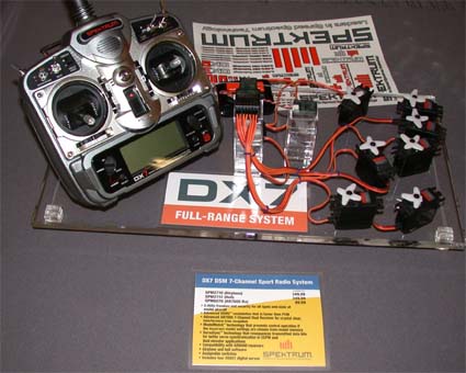
The new Spektrum DX-7 full range
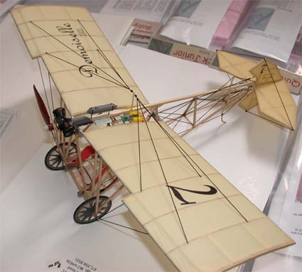
A nice Demoiselle
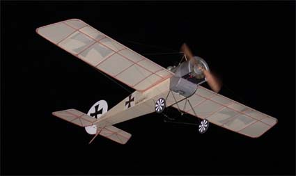
An E-1 on a Flyby
Return to "What's In This Issue"
Some Iowa Planes
From Paul Hartman Lake Mills, IA
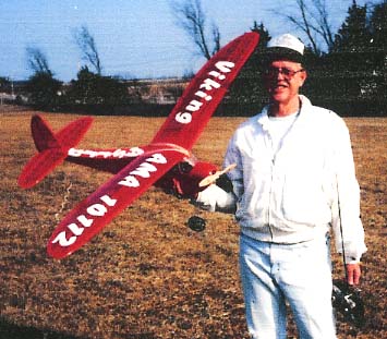
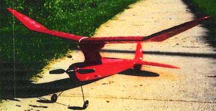
Paul & his Viking
Back in September Paul sent along some photos of his sailplanes, old-timers and other e-powered electrics. He had just then celebrated his 73 birthday. That is a photo of him with his Viking above.
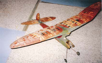
In the resurrection stage
The Zipper above was originally built it in 1950 as a free flight. He stripped the airframe, recovered and converted to RC electric. He has been building and flying models for over 60 years now. Great job on all your planes, and that Zipper is remarkable!
Today as an RC Electric!
Return to "What's In This Issue"
More Planes from Iowa
From Plenny Bates Cedar Rapids, IA
Back in August 2006, Plenny sent some photos taken at the Mid-Am as well as some taken at the Cedar Rapids Skyhawks Electric Fun Fly. I want to especially thank him for the photos of Chris, my new bride, and I at the Mid-Am. They are great and much appreciated!
Here are a few of shots from the Skyhawks' meet.
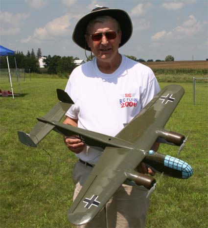
Bob Nelson with the prototype of the Sig Dornier Do217, which he designed.
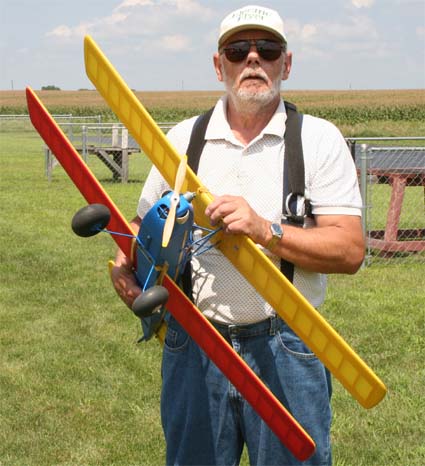
Bob Livin with his "Faultless Chick"
Note to Keith Shaw: They now fly well with the recommended changes.
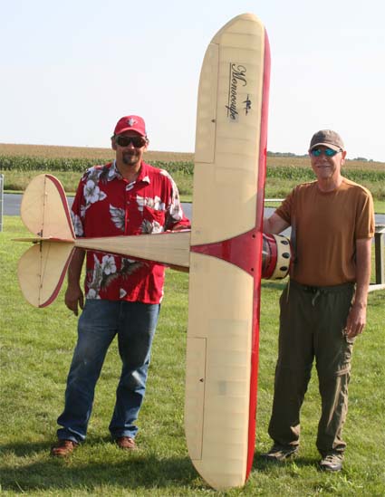
This Monocoupe uses 24 NiCads and a brushed AF 40 w/Super Box and it is still lighter than the gas version!
Return to "What's In This Issue"
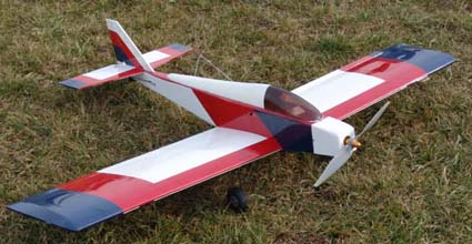
Sportsman Aviation Sonic 500 25-46 ARF Review
By Ken Myers
(1) Preliminary Notes and Thoughts:
This is my second ARF assembly from this company. The first one was the Sportsman Aviation Ryan STA 40 ARF. The STA build thread is located at: www.rcgroups.com/forums/showthread.php?t=557165
My original purpose for this plane was to be a "test bed" for some Milwaukee V28/Emoli cells, the Jeti Spin 44-amp brushless ESC and Spin Box and the Sombra Labs Shadow-3 receiver.
The motor is the BP Hobbies (TowerPro) 3520-6. It is a cheap Chinese (maximum 600/700 watt) outrunner that sells for $52.95 at www.bphobbies.com/view.asp?id=V450327&pid=W428312
My original intention was to use a 5-cell Emoli pack. Testing of the motor with a 5S Li-Po showed that this was a good option.
A Little History
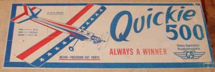
Box from one of my two previously built Spickler Quickie 500s. Today it holds dowels and piano wire.
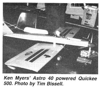
This was not my first Quickie 500 conversion. In early 1984 I converted a Spickler Quickie 500 to electric power. It is featured in Jim ZarembskiŐs Silent Power column in the May 1985 RCModeler/RCM. Jim reported on an Electric Flight Symposium that Jim, Art Arro, Keith Shaw and I put on at Salem High School on October 28, 1984. A photo of my conversion can be found on p. 104 of that issue.
My conversion used an Astro Flight Cobalt 40 direct drive motor, Rev-Up 10x6 wood prop, 18 1200mAh Sanyo cells, Jomar SC-4 or possibly SM-4 ESC, 3 Futaba S-33 servos, 250mAh receiver pack and a Futaba receiver. It weighed about 5 lb. pounds and flew very well as a sport plane for about 6 minutes. It was covered with orange and black Monokote.
The Kit:
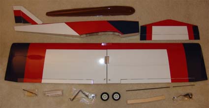
Sportsman Aviation Sonic 500 25-46 ARF $49.99 (Special Buy)
www.hobbypeople.net/gallery/123412.asp
Initial inspection showed no shipping damage.
All of the following weights are out of the box weights with no trimming of the plastic part. All weighing was done using grams on a balance beam scale and then converted to ounces (oz.).
Fuselage: 6.42 oz.
Vertical stab,/rudder/hinges: 0.73 oz.
Horizontal stab/elevator/hinges: 2.32 oz.
Fuselage top/canopy untrimmed: 1.59 oz.
Right wing panel/aileron/hinges/torque rod: 8.68 oz./246.2g
Left wing panel/aileron/hinges/torque: rod 8.90 oz./252.2g
Note: the left wing panel is approximately 1/16Ó shorter than the right wing panel.
Wing joiner: 0.50 oz./14.3g
Landing gear wire/straps/screws: 1.66 oz.
Aileron servo tray & misc. parts: 0.35 oz.
2 Main wheels: 0.53 oz.
2 wire pushrods: 0.73 oz.
2 aileron pushrods/clevises/keepers: 0.30 oz.
Tail wheel/wire/bracket/screws: 0.52 oz.
Total: 33.29 oz. or 943.7g
Measured Wing chord: 9.96875Ó/253mm
Measured Wing Span: 51.3125Ó/1303mm
Measured Wing Area: 512 sq.in./33dm^2
The airframe is covered with an unknown red, white and blue iron-on covering. It is difficult to say what type of wood is used in its construction. Whatever it is, it is quite hard and heavy. A well-designed, well-built balsa airframe of similar type could weigh about 2/3 the weight of this ARF. My guess is that it might be some kind of "shipping container" balsa wood.
The Assembly and Modifications
It should be noted that this is a foam core wing, covered with some kind of wood. The tip ends are either opened, forming bays or have ribs. I hope to never find out the actual construction of the wing.
Wing assembly:
The assembly of the wing was much harder than it needed to be. The torque rod, for the left wing panel, did not move freely. I tried to Dremel it free, but had to remove the trailing edge, free the torque rod from the torque rod bushing and scrape the excess glue from the torque rod so that it would rotate freely in the bushing.
While removing the trailing edge, some of the clear top layer of the cheap covering material pulled away and made the "patch" larger than it needed to be. The clear top layer of the covering on the model pulls easily off of the color layer and the clear layer is easily torn. Of course the Monokote white patch I used did not match the white covering on the model.
There was no mention, in the instructions, of removing the covering material from the torque rod end of the strip ailerons to allow the torque rods to fit into the grove of the ailerons for a tight, gapless fit. Even with the covering removed above the groove on the strip ailerons, I had to use a Dremel tool to make the slot deep enough for the torque rod to ride in and provide a gapless fit. I also had to carefully Dremel and drill out the hole in the aileron stock to align the torque rod correctly in the aileron strip. The way it was originally drilled raised aileron strip end about 1/16" above the mating surface of the wing.
This whole process took a couple of hours, instead of a couple of minutes, before the wing halves could be joined together using 30-minute epoxy.
I modified the aileron servo tray to accept a Hitec HS-85 servo. When I tried to remove the covering for the servo tray, it did not want to come off. The clear layer came off easily, but the white undercoating stayed on and had to be scraped off with a razorblade. The same thing happened when adding the wing bolt reinforcement plate to the underside of the wing.
I put the holes through the wing bolt reinforce-ment plate and wing covering using a heated soldering iron, which works well in opening up iron-on covering. It took about an hour and a half instead of 1/2 an hour for these steps.
Next I tried installing the blind nuts and wing hold down screws. I modified the provided blind nuts by grinding one side flat so that the nut flange would clear the fuselage side.

The provided screws would not pull the blind nuts into position. I opened up the holes in the in the wing hold downs, but by then the cheap screws had already stripped and would not "pull" the blind nuts into the wood of the hold down.
I started the second day of the build by modifying the elevator so that the modified rudder could pass through it.
I tapped the wing hold-downs for 1/4-20 nylon screws and attached the wing.
The horizontal stab was epoxied onto the fuselage using the wing to align it. Again, the hard to remove covering caused problems. It was very difficult to clear it from where the horizontal stab glued onto the fuselage.
The elevator was finished and attached to the horizontal stab. The slot for the vertical stab was extended into the horizontal stab so that a full rudder could be used. The rudder now extends below the fuselage.
On the third day of the build I fabricated an extension for the provided rudder to convert it to a "full" rudder. The vertical stab was epoxied in place. The extended rudder was finished and the modified rudder hinged onto the vertical stab and fuselage bottom. The original push rod guides were removed and the wood they were attached to Dremel sanded out of the former.
On day four, the rudder and elevator servos were installed after modifying the servo tray to accept the smaller FMA servos. New push rods were created for the elevator and rudder using the provided wire and some dowel rod. The aileron servo was installed into the modified servo tray. The ailerons were then hooked up. The transmitter was set up with the name of plane and the servo throws set to the proper direction and deflection.
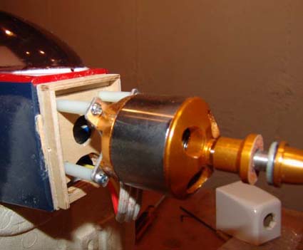
On day five the motor mount/cowl holder, that I had fabricated, was epoxied to the firewall.
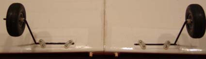
The slots through the covering for the wire landing gear legs in the wings were opened using a hot soldering iron. The main gear and wheels were attached. Flats were ground on the gear wire for the wheel collet's screw to grab. Thread lock was applied to the collet screws and the screws tightened into the collets. I didn't cut off the excess gear wire because I thought that I might have to use larger wheels later.
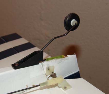
The tail wheel bracket was attached with three screws into CA hardened holes on the fuselage bottom. The tail wheel wire was bent 90-degrees and run through the yellow inner portion of a Nyrod and then epoxied to bottom of new rudder. The tail wheel was positioned and a flat ground for the collet screw on the axle. Thread locked was placed on the screw and the screw tightened on the axle.
The canopy/turtledeck was trimmed and the first coat of paint applied. I ran out of paint, and had to start over with a different paint. The painting was finished later in the day.
On day six, the motor was attached for a quick check of the CG to see where to put the battery tray. The wing was checked to see that it would fit properly with the battery and the rest of the onboard radio components installed.
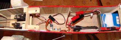
The radio installation was completed by running the antenna wire to the horizontal stab, Velcroing the Sombra Labs Shadow-3 and Jeti Spin 44-amp ESC into the positions shown in the photo. I had to add a 3.5-inch extension to the Jeti Spin 44 to get it out of the way of the battery. Jeti warns against extending the leads from the ESC to the motor, but I had to do it and it is working.
After the first test flight a pilot and instrument panel were added and the canopy/turtledeck glued on using Tacky glue, a good substitute for RC 56. Tacky glue can be found at craft stores and other places that sell crafts.
My fears about the supplied 2-inch wheels being too small for the grass field I fly from proved to be true and the wheels were changed to some 2.5-inch wheels I had on hand.
The flight surface trims were adjusted based on the transmitter trims. The plane was balanced side-to-side by adding parts of a couple of nails to the right wing tip (~0.23 oz./6.5g). For the security of the canopy/turtledeck, it was, again, glued all the way around with Tacky glue. The ailerons were given more throw. New flats had to ground on the axles for the wider wheels. The collet screws were reinstalled with fresh thread lock on the screws.
Some Final Weights:
The painted canopy/turtledeck weighed 1.57 oz./44.4g
The Fabricated Motor plate: 0.31 oz./8.75g
Didn't weigh the pilot and dashboard.
RTF weight w/4S1P Skyshark 4000mAh Li-Po: 66 oz./1870g, CWL: 9.84 oz./cu.ft., WL: 18.56 oz./sq.ft.
RTF weight w/5S1P True RC 4000mAh Li-Po: 69.8 oz./1980g, CWL: 10.41 oz./cu.ft., WL: 19.63 oz./sq.ft.
Flight Report:
Summary November 24, 2006 - November 28
A day-by-day description is available in my Build Log on RCGroups at: www.rcgroups.com/forums/showthread.php?t=604271
It was hard to believe that, for almost a week following Thanksgiving, there was decent weather for flying.
On the first test flight day it was 43-degrees F/6.3-degrees C with a 10-mph/16Kmph wind out of the southeast. The 4S1P Skyshark 4000mAh battery was loaded into the plane. It had been kept warm in a rice bag* until loading it. The prop was the APC 11x8.5E. The plane had been ranged checked at home. Several attempts were made to get off the field. It was clumpy, long in parts and had "critter" trails under it. With the landing gear placed too far rearward in the wing and the small wheels, the plane kept nosing over and striking the prop. With no one at the field, I decided to try a takeoff from a bare ground area at the end of the drive. That was successful, although the plane still wanted to rotate forward because of the poor gear placement.
Once in the air the plane needed a bit of up trim and left aileron trim. Rolls were slower than I like. The climb rate was very good. Loops were as large as I would like to make them. I tried a couple of snap rolls and they were okay.
The landing was a non-event. The plane took off at about 62.5 ounces (as the canopy/turtledeck, pilot, dashboard and larger wheels had not been added yet) and just floated in for landing, even much more than I had expected. It was flying fine on the four-cell pack.
* rice bag - a kitchen towel that has been turned into a bag with a Velcro top, rice added, heated in a microwave to apply on aches and pains of us old folks and to keep Li-Po batteries warm on cool days.
;-)
The following day, three flights were made at the Midwest RC Society field. The temperature was about 53-degees F/11.7-degrees C. The sky was overcast but bright. The wind was from the south at about 5 mph to 7 mph but gusting over 10 mph quite often.
After making several changes as noted in the assembly section, the plane took off from the grass with the larger wheels. It still suffered from trying to flip up on its nose because of the poor gear placement. Using my Skyshark 4S1P 4000 mAh #1 pack, I flew very comfortably for 9 minutes feeling out everything this plane is capable of. It was a good flight with an easy to get to know plane. Refilling the battery the following morning, the AF109 put in 2.283 AH for the nine-minute flight using the APC 11x8.5E prop.
A second Skyshark 4S1P 4000mAh pack was loaded into the plane. Once again the plane tried to nose over on takeoff. It was a good flight and a lot of fun. Several of the fliers remarked about how well it was flying. The flight lasted ten minutes and a refill of the battery the next day showed 2.888 AH put back into the pack.
For the third flight of the day the True RC 5S1P 4000mAh pack and APC 10x7E prop was used. I wanted to try and get some flight shots, so Larry Markey took it off and flew it around for quite a long time. He noted that it had plenty of power and speed for him and how well balanced it was. It sure pays off to get the balance for and aft and side-to-side correct. I took over the controls and about 6.5 minutes into the flight, the motor shut down unexpectedly. I was sure that it could easily do ten minutes. It restarted in the air, I flew a bit, and it shut down again. I kept this up for a couple of minutes and then landed. A great flight!
The next day I measured the voltage of the pack and found that I should have still had quite a bit of flight time with the pack as only 1.720AH were returned by the AF109 charger.
I used the Spin Box (reported on last month) and found that the ESC temperature had reached 100-degrees C and I had the cutoff set at 99-degrees. That explained the on/off behavior of the ESC during that flight. I have since reset the maximum temperature before cutoff to 102-degrees C, the maximum allowed by the controller.
On the third day flying this plane the sky was gray but the temperature was about 57-degrees F/13.9-degrees C. Winds were still from the south, but low enough not to be a factor.
The first flight used the 5-cell pack, and again the ESC started cutting off at about 6.5 minutes. I believe it had hit the high temperature cutoff again, so I have moved the temperature setting up the ESC maximum of 110-degrees C. The rough field did in my APC 10x7E prop on landing.
Two more flights were made using the APC 11x8.5E prop and the two Skyshark 4S1P 4000mAh packs. One flight was about 9 minutes and, using the second pack, the second over 10 minutes.
The plane was flying really well. I did just about every maneuver that I know how to do. Spins are especially nice. The avalanche requires a little different timing than most of my other planes, but turns out well.
On the fourth day of flying, the ambient temperature was nearly 60-degrees F/15.6-degrees C. Winds were out of the southwest at about 10mph/16Kmph with a gray but bright sky. Three more flights were flown. Again, the ESC shut off early when using the 5S1P pack because of it being "over temperature". That is quite disappointing. All flights were good and it is a pleasure to fly this plane.
On day five the ambient temperature was near 60-degrees F/15.6-degrees C. Winds were out of the southwest at about 10mph/16Kmph with a bright blue sky. The first oops occurred. I flew the 5S1P pack and it again shut off again at about 6.5 minutes. I misjudged the landing and kind of nosed in breaking the prop and the right landing gear block area. I decided that the landings and takeoffs with the stock gear placement are just too nasty for me.
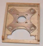
Landing Gear Mod:
After my oopsed landing on November 28, I decided to go ahead and install new landing gear blocks in the correct position. I created the new blocks using:
3/16"x5/8"x 3.5" plywood for the base
1/8"x1/4"x3.5" plywood for the top plates to form the groove
1/16"x1/4"x 3.5" balsa to top the top plates and allow easy sanding to the less than 5/32" diameter wire thickness
3/16"x5/8"x5/8" plywood for the "bottom" block
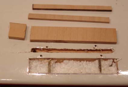
New landing gear block parts
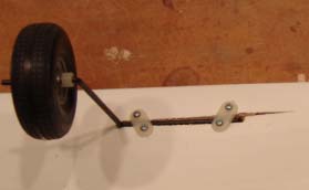
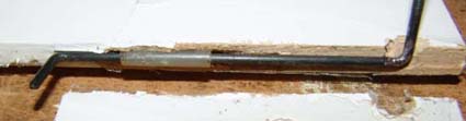
Oopsed landing gear
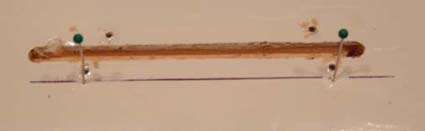
Pins used to find edge of original landing gear
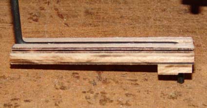
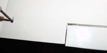
The new landing gear block
I used straight pins to find the edge of the installed blocks and then marked, cut out and Dremeled out the new area for the landing gear blocks. I was pleasantly surprised to find, not just foam, but some kind of wood actually holding the landing gear blocks in place.
The new blocks were epoxied into place and then more epoxy was added to fill any gaps.
The original groove for the landing gear was filled with balsa and then the whole landing gear area covered with white iron-on covering.
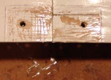
I cut off about 1/8" from the landing gear wire going through the block to make sure it didnŐt penetrate the top sheeting. The holes were carefully redrilled to clear any epoxy from them. The gear were reinstalled and the process done in just a few hours, including the epoxy drying.
I have not had a chance to fly the plane with the new gear placement, but I am sure it will be well behaved on takeoffs and landings now.
Conclusion:
The Plane: When properly balanced and trimmed the plane flies well and is fun to fly. There are several building annoyances and a major design flaw.
The good stuff:
1. The plane is easy to fly and land and performs all sport pattern maneuvers well.
2. It is inexpensive.
The Not So Good stuff:
1. The landing gear is misplaced on the wing causing nose-overs and other difficulties on takeoff and landing on "tufted" grass fields.
2. The wing hold down screws and blind nuts do not work well as supplied and the screws are easily stripped.
3. The covering material is not easily removed for gluing on the necessary pieces and is just plain bad.
4. The supplied wheels are too small for the grass fields I fly from.
5. The wood used in the construction of the model is too heavy.
6. The canopy/turtledeck is difficult to fit as the top of the fuselage is not flat and the bottom of the canopy/turtledeck is.
Other notes:
If a three cell Li-Po pack is used, it would be a good idea to move the servos into the area forward of where they are located as the unit is shipped.
I have my CG set at about 3.25" back from the leading edge of the wing, and that seems just about right for my style of flying.
The gear axles should be lined up under the leading edge of the wing.
Basically, you get what you pay for.
The Jeti Spin 44:
The ESC seems to perform well with a 4S1P pack but has caused endless problems with premature cutoff when using the 5S1P pack. The switching BEC seems to be a nice, built-in function.
The Jeti Spin Box:
It works well to fine tune the parameters of the ESC and is relatively easy to use. I like the idea that it is easy to take to the field to make changes, just like when I use my Emeter with my Hyperion ESC.
It does not appear to be very accurate in logging data. There are many unexplained functions and the instructions need a major revision and update to include the servo testing function.
The BP Hobbies BP 3520-6:
It performs as expected, is reasonably efficient and is a good value. The "X" mount needs a major revision to allow the motor mount screws to fit properly.
The Sombra Labs Shadow-3 Receiver:
This is the third one I've had and the first one to work for me. It appears to be working well, but I have not flown it in a rich "RF environment" yet.
Sonic 500 Postscript
My favorite setup is the BP 3520-6 using the 5-cell 4000mAh True RC pack and the APC 10x7E prop. Lots of fun! I need some more 5S packs! :-)
Return to "What's In This Issue"
| 
