 |
Flying High With Electric Power!
The Ampeer ON-LINE!
Fly the Future - Fly Electric! |
Site Table of Contents
| President: | Vice-President: | Secretary/Treasurer: |
| Ken Myers | Richard Utkan | Rick Sawicki |
| 1911 Bradshaw Ct. | 240 Cabinet | 5089 Ledgewood Ct. W. |
| Commerce Twp., MI 48390 | Milford, MI 48381 | Commerce Twp., MI 48382 |
| (248) 669-8124 | (248) 685-1705 | 248.685.7056 |
 | ||
| Board of Directors: | Board of Directors: | Ampeer Editor |
| David Stacer | Jack Lemon | Ken Myers |
| 16575 Brookland Blvd. | 8908 Sandy Ridge Dr. | 1911 Bradshaw Ct. |
| Northville, MI 48167 | White Lake, MI 48386 | Walled Lake, MI 48390 |
| 248.924.2324 | 248.698.4683 | 248.669.8124 |
| Mailed Ampeer subscriptions are $15 a year US & Canada and $20 a year world wide. FREE on-line! | ||
| The Next Meeting: Date: Thursday, February 5 Time: 7:30 p.m. Place Ken Myers' house | ||
|
When subscribing to or renewing the paper version of the Ampeer, please make the check payable to Ken Myers. We do not have a DBA for the Ampeer or EFO. Thanks, Ken Why CWL Gives About the "Number" For CWL in Imperial and Metric Units In the January issue I suggested that maybe a mathematician might be able to answer why the CWL works out to be almost exactly the same in Imperial units (oz./cu.ft.) and Metric units (Kg/M3). It turns out that our on EFO member, Roger Wilfong, knew the answer. Thanks Roger!
Ken, Here's the reason the numbers for CWL in metric and imperial units are the same. In imperial units,
converting the units to metric
Moving the volume conversion factor to the outside of the term and regrouping the numerator, we get CWL[metric] = (0.0283495231 * (oz * kg/oz)) / (0.028316846592 * (ft * m/ft)^3)
In other words, the conversion factor for converting cubic ft to cubic meters (0.028316846592) is about 0.1% different from the conversion factor for converting ounces to kilograms (0.0283495231). Since the later is in the numerator and the former is in the denominator, for all intents and purposes, they cancel out.
It sure is, and thanks Roger! KM I also received this explanation from Stefan Vorkoetter.
It's not exactly the same, just very close. There are approximately 35.27 ounces in a kilogram, and coincidentally, approximately 35.31 cubic feet in a cubic metre, so converting from oz/cu.ft to kg/m^3 is a matter of dividing by 35.27 (to get kg/cu.ft) and then multiplying by 35.31 (to get kg/m^3). In other words, converting from the former to the latter requires multiplying by 35.31/35.27, which is about 1.001.
Stefan Vorkoetter
Thanks also to all the others who wrote in with basically the same explanations! Much appreciated. KM Handy Nylon Motor Spacer Tip
I'm assembling a BITSA (bits a this and bits a that) Goldberg Cub. I was given a bag full of parts and had a partial kit, also a gift. When I'm building something like that, my Yankee kicks in and I try not to spend any money that I don't have to. I needed some standoffs for my Himax 5030 (itself a half price purchase). I had some 1-inch nylon pieces from ACE, but I needed some 1/2 inchers. As I was plowing around my "Nylon Salvage" bin I came across a bunch of nose-gear mounts. Bingo! I cut off the mounting tabs and had my nylon spacers. Then I realized that the tabs could also be used (they are a little less than 1/4 in.). Since I rarely use nose gear I now have a good supply of spacers. A Tiger Kitten Under Way
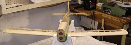
I received an email from Nick with a couple of photos of his Bob Benjamin TigerKitten under construction. Bob Benjamin is an excellent model builder and designer. Bob's original 1989 design of the TigerKitten was published in the September 1991 Model Aviation and then kitted by ACE R/C. It was followed by Bob's TigerCat, a larger version, in the January 1993 Model Aviation.
Here is another photo of Nick's under construction to pique your appetite. 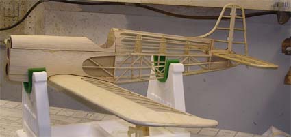 CWL Questions
I received an email from Bill with a questions about CWL/WCL. KM Hi Ken, Just finished reading your latest Ampeer. As always, it was very good. Questions: I am building my own design from scratch. It is about ready for cover. Therefore I have been able to make some close estimates regarding CG location and RTF weight. I have two motor choices: 1 would be a BP 28-14 motor that would be setup to pull 35A max with a 2200mAh 3S1P LiPo. 350 watts. 2nd choice would be an A20-22L that pulls 15A on the same battery. 150 watts.
The CWLs are 4.6 and 4.3 respectively. Now, wouldn't the 350W A/C fly quite differently than a 150W setup even though the CWLs are about the same? Yes and no. The "flyability" will be basically the same, but the performance will be quite different. The CWL is used to describe how difficult the plane will be to fly, compared to other similar types with the same CWL. You plane, whether powered with either motor, will fly at about the same difficulty level when flying on the wing. The thing that is different is the potential performance. The 350 watts in system can either fly faster than the 150 watts in system, have more thrust or even have more of both.
Also, I never see any reference to "Span Loading" or oz./foot of span. I know in full scale aircraft the ability to climb is greater with a longer wingspan. (assuming you could interchange two wings on the same aircraft without changing the weight). For example: A 150 hp Citabria with flaps has about 18" more span than the same aircraft without flaps. I assume the span difference is only to accommodate the flaps. The flapped or longer span aircraft will tow advertising banners much better than a non-flapped aircraft. This is based on about 3000 hours experience in Citabrias towing banners. When I say "better", I am referring to initial climb to altitude performance.
Bill I have never seen a formula regarding "flyability" or related to the aspect ratio. I don't know a lot about aerodynamics but according to Martin Simons, "... doubling the aspect ratio halves the induced drag coefficient."
Arming Switches for the Power Battery Since I mentioned switches last month, I received quite a few emails regarding them, and everyone one of them stated that they believe they are a good safety idea.
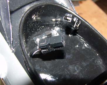 I have a switch in my Ryan STA that is very similar in concept to the one that I showed last month from Maxx Products. The plane uses a 4S 4000mAh Li-Po for power. I installed the switch because I prefer to take two 6-minute flights rather than a 12-minute flight. After the second flight, I remove the struts and wing and then remove the Li-Po pack. I do not leave it in the plane for transport or charging. Here are some of the emails I received concerning power switches:
On switches, I agree that charging outside the aircraft should be done with Li-Pos. However, I think an on /off switch would be a safety addition. Once we plug the main battery in, the motor is ready to go and an inadvertent bump of the throttle could cause trouble.
From Dave Segal, Keystone RC Club I wanted to add a comment to the question raised by John Mrozinski on arming switches. Bob Kopski pointed out in his column in the August, 2004 issue of Model Aviation that brushless motor ESCs will kill any arming switch due to the very large capacitors in the ESCs and their low resistance. He said the effect is equivalent to a "dead short". He also explained that while the arcing will occur with Anderson Power Poles the ingenious design of the contacts limits the arcing to the non-critical tip of the connector. Bernard Cawley is given credit for this observation. Thanks for the reminder about a possible problem. You can find the solution to the arcing problem at mgm-compro.com/pdf/en-antispark-d230808.pdf. When connecting a Li-xxx pack to the controller, strong sparking commonly occurs. Fast charging of the controller filter capacitors causes this. The higher the voltage (the higher the cell count), the lower the internal resistance (and the better the quality of the pack). The better the capacitors in the controller and the higher the capacity of the capacitors, the bigger spark occurs. Besides the small shock (due to the sparking), the charging current of the capacitors may be in, extreme cases, so great that damage or destruction of the capacitors occurs.
|
|
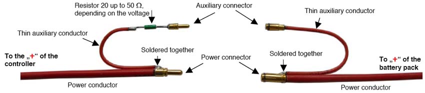
Connectors, as well as the resistor, are insulated by heat shrink tubing. 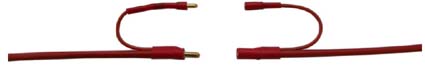 How to connect the battery:
There are also no requirements on the resistor, any type is sufficient, e.g. metallized 0.6W, size 0207, value between 20 to 50Ω depending on the voltage of the battery pack. E.g. for 4 - 6 Li-po use 20�, for 10 Li-po 33�, for 12 up to 15 Li-po 51Ω. However, it is not necessary to use these exact values because of wide variation. Connect the new auxiliary connector first. Capacitors are charged with small current. Sparking will not occur. 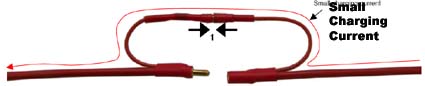 Now connect the power connectors (sparking will not occur). Main current to the controller and the motor during operation passes through these power connectors and conductors. 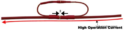 From Scott Paschen Ken, here is a quick story of what could have been a real mess and was a smashed up airplane. Also a good example of why there are AMA rules.
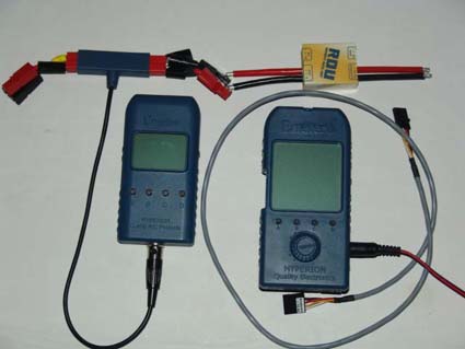
Emeter II: First Impressions and Use
It is FINALLY here!
"Introduction
The Emeter/RDU is reverse polarity protected. Hooking up the main power pack will not "kill" the units, but it will not function properly.
Scorpion S-3020-11T & Scorpion Commander V2 45-Amp ESC Review
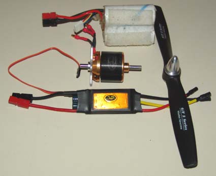
I have a "new" 3S1P "A123" design in progress and I wanted a new motor and ESC for it. I wanted to try the Scorpion brand, as I have been recommending it to my flying buddies for quite a while now. I have found that a 1200ish Kv works well with a 3S "A123" pack and 10-inch diameter props from my experience with my Son of Swallow. The SoS uses a Hyperion 3019-10, but my particular motor is odd, because it has a Kv of just over 1200, as I've noted before here in the Ampeer. The Hyperion 3019-10 weighs 145g. I looked at the Innov8tive Designs site (http://www.innov8tivedesigns.com) and noted that the 3020 series motors weigh about 154g, which is close enough, but the highest Kv available is the S-3020-12 with a Kv of 1088. I know that the winds and Kv are pretty much proportional. I multiplied 12 (the winds) * 1088 (the Kv) and divided that answer by 1200 (the Kv I wanted). (12 * 1088) / 1200 = 10.88, which indicates and 11 wind.
No Load #1 10-cell 1700mAh NiCad pack
No Load # 2 6-cell 2000mAh NiCad pack
APC 9x7.5E
parkzone T-28 9.5x7.5
APC 10x7E
Master Airscrew 10x8 G/F 3 Series
The Specifications:
 Earlier I mentioned that Scorpion did not produce a 1200Kv motor at the weight I wanted. They do have a S-3014-16 with a stated Kv of 1187 and weight of 122.1g/4.3 oz. While this may appear to be a better choice because of the weight, it isn't. Using Drive Calc figures for the 3S "A123" pack and the MA 10x8 G/F 3 Series prop:
|
To Reach Ken Myers, you can land mail to the address at the top of the page. My E-mail
address is:
KMyersEFO@theampeer.org
EFO WEBsite