In Part 1 of this series of articles we discussed the basic requirements for a successful Speed 400 powered design. Part 2 will give you some ideas for building a light and sufficiently strong airframe for your own Speed 400 design.
It will come as no surprise to anyone who knows me that I prefer to work in composite materials. Even though I cut my teeth on balsa, and still have a fond place for it in my heart, almost all of my recent designs consist mainly of foam, fiberglass, carbon fiber, Kevlar and epoxy. That's not to say that balsa is inferior! In fact, I will spend a fair bit of this article discussing balsa and how to use it in conjunction with 'high tech' materials to build a very light structure. I will also discuss all-composite airframes.
The upper (or lower) cradle goes under the vacuum bag (not inside) to keep the wing flat. Once the wing is positioned in the cradle, place the upper cradle on top of the bag and add a couple of bricks to press the wing flat. Seal the bag and draw vacuum (17-24 inches). 24 hours later, peel out and trim the flashing from your nearly finished wing. It sounds simple, and it really is, but it does require a fairly high initial investment in equipment. Which leads me to the next method....
Everyone has seen the heavy brown paper that is used for wrapping boxes. Commonly known as Kraft paper, it is 60# untreated brown paper. The fact that it is untreated means that it will soak up resin (which is a good thing for our purposes). This paper can be used in place of fiberglass for wing skins, and can be used on fuselages provided there aren't too many compound curves. For wings, fold a piece of paper and lay the wing core into the folded paper trailing edge first. Now mark around the core and trim the paper to fit flush with the edges. Use a foam roller to apply epoxy to the inside of the brown paper then place the core inside. Roll some epoxy on the outside (to seal the paper) then put waxed paper or coated freezer paper on the outside. Now put the whole mess back in the cradles. Place on a flat bench and stack weights on it until the epoxy cures. This will give you a wing that is similar in weight to one skinned with fiberglass, but doesn't require vacuum bagging. Of course, it's pretty dam ugly, but hey, it's cheap! If you want it to be pretty, swipe some light spackle on the wing, sand smooth. Now you can prime and paint.
I hope this gives you some ideas for lightweight construction techniques. Next time we'll present the plans for either the Brownie or Speedie (haven't decided which) so you can build a Speed 400 racer and go fast, turn left.
Return to "What's In This Issue?"
Sanyo Date Codes
via WATTS CURRENT - Aug. 1996
Doug Ward, editor, R.D. #1, Box 189, Irwin, PA 15642
| Year Code | Month Code |
| R-1987 | A-January |
| S-1988 | B-February |
| T-1989 | C-March |
| U-1990 | D-April |
| V-1991 | E-May |
| W-1992 | F-June |
| X-1993 | G-July |
| Y-1994 | H-August |
| Z-1995 | I-September |
| A-1996 | J-October |
| B-1997 | K-November |
| C-1998 | L-December |
If for example, you find a ZE code, the chart reveals that the cell was made in May 1995.
Return to "What's In This Issue?"
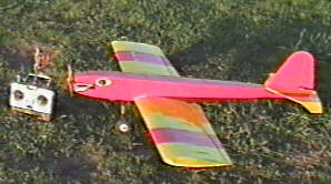
The Speedy Bee by Clancy Aviation
from Dereck Woodward - e-mail: woodwadd@erols.com
Subject: Speedy Bee for the Plane Ratings
Ken
The Speedy Bee by Clancy Aviation, I'll give it a four star rating.
Mine has micro RC gear with an Astro 05G, eight 1700's and Master Airscrew props - either an 11 x 9 wooden Electric or 11 x 7 "S" series. Flying weight is 51 ounces -
my only gripe - with more "Lazy Bee" structure instead of "convenience", it would be lighter, fly better. Mine is absolutely stock - for a kit review in EFI. The best die-cut kit I've built, cutting and parts accuracy are outstanding. Three sheet plan is the same one RCM sell as a construction plan, with all parts and even the "works" colour scheme shown for templates. Monokote covering doesn't help the weight - should have used Micafilm. Kit has many of those little details that make it outstanding - you even get a pre-cut and printed set of parts to make up the full dashboard panel for the Williams Bros. pilot shown on the plan.
I flew for a while with lower control throws, now have vast throws - ailerons 1-1/4" each way, elevator and rudder approaching one inch. Take - offs are easy to keep
straight, but needs a hefty pull to lift off. Suspect suction between that 14" chord wing and the ground - but this is no problem and the subsequent steep climb out looks cool. Landings - you can put it down just where you want. I have flown mostly off hard surfaces. Slow and fast flight - well, there isn't that much difference between the two!
Aerobatics are as wild as my Lazy Bee, with real inverted capability added. She'll do presentable four point and slow rolls and needs little down stick for inverted. All the usual loops, rolls and combination manouvres are there, the stall is straight ahead and docile. The wing will not stay stalled long enough to spin or snap roll - the maximum roll rate is fast enough to imitate an Avalanche loop that few will argue about! Still shies away from outside loops, the flat bottomed wing is not going to play that game. Attracts attention like little else!
Speedy Bee is growing on me fast. Well recommended for the extrovert flier who wants something different looking. Don't bother with low power combos - I did fly her on a Graupner FG3 motor/box combo, spent all the flight on full power just to keep it fun. If you want relaxation, go for the long wing Lazy Bee, Speedy Bee is for moving, not
loafing.
Return to "What's In This Issue?"
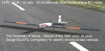
A Win for MaxCim!
from Tom Cimato - e-mail at: MaxCim@compuserve.com
57 Hawthorne Dr., Orchard Park, NY 14127-1958 --- Phone/Fax 1-716-662-5651
Hi Folks,
MaxCim Motors contributed to a winning effort!!
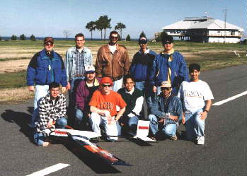
The University of Illinois chose to power their winning entry with a stock
Max15-13Y Brushless motor with 3.53:1 Model Electronics gearbox and our Maxu35-25NB Digital 25 cell Speed Controller. They
used a 15x12 prop. I made the 19 cell - RC2000 packs for them, each weighing 39oz.
Here is the statement from the team leader describing the winning effort:
"I am pleased to report that we have won the Cessna/ONR Design/Build/Fly
contest. The flight of record was 12 laps (about 12 minutes), which was good enough to win by a large margin. We attempted
more flights later to see what we could do. We completed a 16 lap flight, but did not land legally, so it didn't count. Finally, we
flew the aircraft until the batteries were exhausted and completed 20 laps (about 16-18 minutes), again we had some landing
difficulty. One reason why we were not careful about landings was because, we knew that we had already won and our first
concern was the safety of the aircraft.
The entire propulsion system performed flawlessly."
This is a perfect example of the wide range of performance and the part throttle
efficiency that we offer the average E-Flyer.
BTW, Virginia Tech was second, powered by an Astro 15G, and Texas A&M was
third with power by Aveox, West Virginia Univ. was 5th with a Max15 setup also.
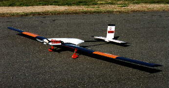
The Univ of Ill. plane has a 12 ft. wingspan with a 12" chord and a Clark Y !!
airfoil. Final weight is about 15lb. and they flew at an average of 35 fps.(24 mph - I think!).
Regards,
Tom Cimato - MaxCim Motors, Inc.
The contest description follows:
The AIAA, through the Applied Aerodynamics, Aircraft Design and Flight Test
Technical Committees, is pleased to announce the First Annual Student Design/Build/Fly Competition. The contest will provide
engineering students with an opportunity to apply the knowledge gained from their analytical course work to a UAV class aircraft
design. Student teams will design, fabricate, and demonstrate the flight capabilities of an unmanned electric powered radio
controlled aircraft with the maximum range on a limited battery weight. The effort must produce a well balanced aircraft with good
flight handling qualities and practical and affordable manufacturing requirements along with high vehicle performance. To maintain
a fresh design problem for each years student team the performance objective will be updated for each new contest year.
Trophies will be presented to the 1st, 2nd and 3rd place teams, and the winning team will be invited to present their design at a
future AIAA technical conference.
Objectives:
Aircraft will be designed to provide the maximum range for a given battery weight.
Range will be determined from the maximum number of complete laps made over a specified flight course.
Each aircraft must:
Complete a take-off over a 10 ft obstacle within a marked 300 ft runway area.
Complete as many laps of the flight course as possible with the available energy. Land within the marked 300 ft runway area.
VIII. Aircraft Requirements
The aircraft may be of any size and configuration except rotary wing or lighter-than
air.
Must be propeller driven and electric powered with an unmodified, over the
counter model aircraft electric motor. May use multiple motors and/or propellers. May be direct drive or with gear or belt reduction.
For safety, each aircraft will use a commercially produced propeller.
Teams may modify the propeller diameter by clipping the tip.
Must use over the counter NiCad batteries. Battery pack weight must not exceed 2.5 lbs.
PHASE
Each aircraft will carry a removable 7.5 pound steel payload. The payload may be
segmented into no more than 3 pieces, each of which must be rectangular in shape. (Wedges, cylinders, or other "sculpted" shapes
are not allowed).
Aircraft and pilot must be AMA legal. This means that the aircraft TOGW
(take-off gross weight with payload) must be less than 55 lb.
IX. Flight Demonstration
Aircraft will be judged on the maximum number of complete laps over the specified flight course.
The course consists of:
An un-assisted takeoff over a ten foot obstacle (ribbon) within a marked 300 ft
zone.
Aircraft will then fly as many complete laps as possible over the specified course.
The course will consist of two 180 degree turns at least 700 feet apart. (Turn spotters will be located 200 ft from either end of the
take-off/landing zone.) On the downwind leg of the first lap the aircraft will make a level 360 degree turn to the right and a level
360 degree turn to the left. Both turns must be initiated after passing the upwind spotter, and be completed before passing the
downwind spotter.
Flight altitude must be sufficient for safe terrain clearance and low enough to
maintain good visual contact with the aircraft. Decisions on safe flight altitude will be at the discretion of the flight line judges and
all rulings will be final.
After completing as many laps as the team calculates is possible with the available
energy the aircraft must return and land within the original marked 300 ft zone.
Total flight time must be at least 3 minutes. No components may be dropped from
the aircraft at any time during the flight. Upon landing, the aircraft must be capable of a second flight with no repairs or service
other than recharging the batteries, and possible replacement of the propeller(s).
Partial laps do not count.
A one lap penalty will be added for any aircraft which lands on the runway, but not
within the marked 300 ft. landing zone. Aircraft which land off of the runway will receive no score for that flight.
Each aircraft will be presented for judging prior to the first flight with the payload
installed. The team will then demonstrate removal of the payload in no more than 10 minutes. Each aircraft will make one
qualifying flight of two laps of the course with the payload removed (to demonstrate acceptable handling and cg location without a
payload) prior to being allowed to make any scored flights with the payload. Multiple scoring flights may be made as desired and within the available contest time.
(Thanks, Tom, for the information. It is nice to see future engineers using
e-powered flight. Congrats on the win too! km)
Return to "What's In This Issue?"
Keith Shaw's Repowered M35b
from Keith Shaw, 2756 Elmwood, Ann Arbor, MI 48104
Hi Ken,
It was good that the weather held off long enough that we could fly together on
Sunday, and that you could see and believe the performance of the Messerschmitt. Here are the requested specs, and a little
history.
 Note that this is the M35a, talked about in the text. Note that this is the M35a, talked about in the text. | History: Europe had fierce pecision aerobatic contests in the 20s and 30s.
Germany entered some of the contests by the late 20s. At end close of WW1, the Treaty of Versailles restricted German aviation
by imposing a 25hp engine limit. Because of this restriction, Germany developed gliders and sailplanes to a fine art to keep the
interest in aviation alive. Also several civilian manufacturers (Klemm, Beucker, Messerschmitt) produced some very efficient
powered aircraft (more like powered gliders) for club flying and training; some of these were even capable of decent aerobatics.
By 1930, the restrictions on powered flight were relaxing, so somewhat larger engines began to showing up in these planes,
sufficient to let them enter European aerobatic contests. |
The original M-35 was a two-seat low wing aerobatic trainer with a high aspect
ratio wing (about 8:1), powered by a 100hp Siemens radial. It did quite well, but not in the money. A modified, "souped up"
version, the M-35A emerged, with a strengthened wing spar, wheel pants, coverable front cockpit, and the larger 150 hp Siemens
radial. Willi Stor suceeded in winning the German National Aerobatic championship in 1935 & 1936 with this plane, and
placed 2nd in the European Championships.
To try to win all the cookies, a single further variant (M-35B) was produced with a
reduced aspect ratio wing, single seat, and an aircooled in-line 250hp Argus engine. It was reported to be dramatically better, but
competition had also stiffened, and it could not compete with the advanced Beucker designs.
My original model was the M-35A of Willi Stor's, built in 1990, badly damaged in a
freak accident with a thermal (!) a few years later.
Recently, I rebuilt it as the M-35B, to test out the MaxCim "Y" motor
on various gear ratios and a fairly high cell count (up to 20 SCRC)
The specs are:
span: 63", area: 630sqin. weight: 6.2lbs., airfoil: NACA 1414, wing loading 23 oz./sq.ft., max input power loading: 78
watt per pound
The present power setup is the "Y" motor with a new Astro 05/15
super gearbox (ratio 3.6:1), MaxCim controller, and 20 older SCRC cells. You have to bore out the pinion to 3/16", or have
Tom Cimato (Mr. MaxCim) do the modification for you. Tom recommends using Loctite #680 to mount the pinion, rather than
just a press fit, as the shaft is stainless steel.
This combination turns a cleaned-up modified Zinger 13/6-10 at 7.2K, while pulling
only 23 Amps!
Performance is invigorating; it can do easy vertical rolls, vertical eights, rolling
circles, outside turns, lomcevaks, discus tumbles, along with all the "normal" loops, eights, rolls, point rolls, snaps and
spins. What is unique is that I am averaging 10+ minutes of these continuous, rigorous aerobatics! The only time I am at
full power is for the heavy vertical stuff or high drag maneuvers, the rest of the time is at half throttle or less.
Definitely a worthwhile rebuild, and a big "Thank You" to MaxCim for
a great power system.
Keith
Return to "What's In This Issue?"
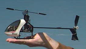
World's Smallest R/C Helicopter?
Alexander Van de Rostyne --- e-mail at: mailto:Alex@staf.planetinternet.be
Visit his site to learn more at: http://www.planetinternet.be/pixel
(I had asked to use some pictures and text from his site. km)
Thanks Ken, (most recent e-mail)
| No problem taking pictures and some text (I only want you to mention that
copyright stays on my side).
It is about any modellers dream to get his project shared with collegues. I am no
different, and I am proud of what I have done...You even could help me. I am now trying to optimize all elements. One of the
areas of research is batteries (off course!).I am currently flying on 8 50 mAh Sanyo Cells (NiCad). This gives me about 1 minute
flying. The 75 mAh gives me 1 minute and 30 sec. If you could help me find better batteries (lower internal resistance, higher
capacity at lower weight, or even non rechargeable ones, etc), that would be great. |
I am sitting on the edge of different technologies, and have to go for the best, almost at any cost.
For you info, current draw is 1.3 amps in hover.
(earlier e-mail)
I have just finished the development (April '97) of what I believe to be the lightest
full RC heli in the world. It is electric powered, has conventional control mechanics (swashplate, Stabiliser bar, tailrotor, 3 gram
servo's, etc).
The model flies perfectly in my livingroom. I will soon put sugar in my coffee with
the heli...Stability is like the much bigger traditional RC helicopters. Total weight including 50 mAh batteries is 126 gram! I will
take off some more weight to go under 120 gram. It may please you that I use the ICARUS piezo (without the case and the long
and heavy servo leads it weights in at 5.3 grams!) for the tailrotor.
Maximum flightime reached today is 1min 30seconds in hover with Sanyo 75mAh NiCad batteries (8 cells, total power requirements are about 1.5 Amps for hover, lift off weight at 138 gram). Going to higher capacity (110mAh) does not seem to add flightime. I am now looking at optimizing the flightime. Can someone give me a hint where to find other batteries (rechargeable or not).? Internal resistance seems to be a problem for the small size NiCads.
Weight is 4.4 ounces batteries included.You can check it on my homepage
http://www.planetinternet.be/pixel
Alexander Van de Rostyne
Belgium
Return to "What's In This Issue?"
The E-Zone & a Sport Scale PT-19
As many of you know Jim Bourke runs a fantastic E-site
on the World Wide Web at http://www.ezonemag.com He puts out
a monthly, on-line newsletter, runs the eflight mailing list and provides great e-flight
services. What prompted this notice is that I had noted a construction article for
a really nice AF40G PT-19 Sport Scale in the articles, designed by Bill Bowne. Plans are
available through the E-zone.
Please add $3 for domestic US or Canadian shipping and handling. �Overseas shipping and handling
charges are $8. Provide the
plan #, mailing address, phone number, and a check with your order.
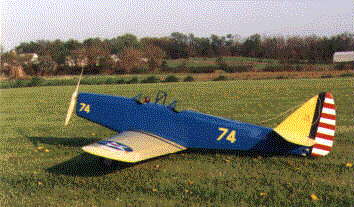
Photo & Model data courtesy of Jim Bourke and Bill Bowne
Model Data |
Wing area: 750 sq. in. Span: 72 in. Airfoil: Clark YH Weight: 120 oz.
Wing Loading: 23
oz/ft. sq. Motor used: Astro Flight Cobalt 40 Geared Number of cells: 20
Propellor: 13 X 10
Watts/pound: 53
The plan number for the PT-19 is 003 and is $20.
Mail your order to:
The E-Zone, 501 Goodwin Dr., Richardson, TX �75081 |
Return to "What's In This Issue?"
New Airfoil Plotting Program for Window '96
from Dr. Patrick E. Hanley --- e-mail at: hanley@hanleyinnovations.com
or visit his WEBsite at http://www.hanleyinnovations.com
Dear Mr. Myers,
I produce a Windows 95 software for plotting templates NACA 4- and 5-Digit
airfoils. Would you be interested in adding a link to my site on your WWW page? (I did. km)For more information,
please visit my site at: www.hanleyinnovations.com/air_16.html
(For those of you without an InterNet Connection, the following info comes directly from his site. If you have a
connection, access his site to learn even more. km)
Hanley Innovations' Visual Foil
VisualFoil, �a NACA Airfoil Analysis & Plotter, is�a MS Windows
95 based numerical tool that computes the lift and moment coefficients for NACA 4- and 5-digit airfoils. The airfoil analysis is
based on a vortex panel method for an incompressible ideal flow. VisualFoil can be used to compute the theoretical behavior of
NACA 4- and 5- digit airfoils for various flap and angle of attack settings. The program is an excellent tool for investigating the
characteristics of NACA 4- and 5-digit airfoils for your next airplane design, plotting of rib sections or theoretical evaluation of an
airfoil response to angle of attack and flap location and deflection changes.
Perform Online Analysis and Airfoil Plotting
- Immediate analysis of NACA 4- and 5-Digits sections
- Lift coefficient �
- Moment coefficients
- Angle of attack for zero lift
- Center of�pressure location
- Effect of plain flap deflection
- Templates for ribs can be produced in a matter of seconds
- Plots allow for skin thickness
- Large airfoils (72"+ depending on airfoil thickness)
- Tapered airfoils can be plotted.
- Effects of plain flaps can be analysed
- Excellent tool for exploring airfoils concepts for model airplane construction
- Excellent teaching tool for undergraduate aerodynamics
- Informative manual is available
Ordering
VisualFoil can be purchased by mailing a check or money order�for
$25.00 U.S plus $3.00 for shipping and handling to:
Hanley Innovations, P.O Box 870, Storrs, CT 06268
Computer Requirements
VisualFoil Requires a PC running MS Windows 95/NT.
More Information?
For more information, please contact: sales@hanleyinnovations.com. or call (860)
423-4060.
Thank you.
Patrick
Return to "What's In This Issue?"
Info and tips from Jim Yuzwalk
e-mail at: jjy@eaglequest.com
Hi Ken,
I thought I'd share a few helpful hints with you:
1. To fasten my 7-cell-battery pack in my Electro-Streak I am using Radio Shack's cat no. 64-2360, Superlock Fasteners, for $2.99. They have a much stronger locking action, (about 5 times better), than normal hook & loop (Velcro) fasteners. I used them last year, and they worked quite well.
2. The other item I just found is Radio Shack's cat no. 278-1555, 10 ft. Ground Strap, for $2.49. This is great for interconnecting your homebrew battery packs. The ground strap is about 5/32 in. wide and should provide a very low impedance current path.
Maybe this information can help some other flyers. If so feel free to use it.
Thanks again,
Jim
P.S. I purchased the Astro 112D today from Tower (I prefer to buy stuff made in the USA). I also bought 14 2000SCRC
Sanyo cells from B&T racing for about $6.70 each. It was great talking to Billy at B&T. They are very RC car
oriented, but appreciate us E-Flyers as well. Hopefully I'll have the packs done soon!
And More from another E-mail
I recently subscribed to Sailplane & Electric Modeler magazine. All I can
say is WOW! I heard about it from the E-zone mailing list, and I think you mentioned it as well in a past issue of the Ampeer. At
any rate, its nice to see a real magazine with an electric focus. Hopefully they will get more subscriptions from other E-Flyers.
On another note, I just finished building two seven cell Sanyo RC2000 packs. I
bought an 80 Watt Weller soldering iron, intended for stained glass work, to solder the NiCd's together. It worked beautifully! Its
large 1/4 inch tip has quite a bit of thermal mass and the 80 Watt element gives you about a 950 degree tip temp! The iron also
comes with a massive 3/8 inch tip which is just a bit too large. The 1/4 tip makes very quick and clean solder joints between the
NiCd and the braid. Very short thermal contact time required to make the connections which means little, if any, cell damage. I
noticed that Radio Shack's largest iron was 40 Watts with a pencil tip. My older iron was a 60 Watt Weller with a pencil tip (tip
didn't have enough thermal mass, and I had to use excessive contact time to heat the NiCd). The 80 Watt iron probably requires a
bit of soldering skill to avoid damaging the NiCd's; I've been soldering for a bit over 20 years. But, maybe its not a bad
recommendation for others (It's definitely better than those underpowered pencil tip irons for this kind of job). Its actually a
Weller model SPG80.
(Thanks Jim. Lots of good tips. I've used the Radio Shack Superlock
Fasteners myself. I also use a stained glass iron for making up packs. Have for years. I think you are less likely to harm
the cells, since you are on them for such a short time. Sailplane & Electric Modeler can be reached at: Sailplane &
Electric Modeler, P.O. Box 4267, W. Richland, WA 99353 � (509) 627-0456 WEBsite is:
http://www.Sailplanemodeler.com/" km)
Return to "What's In This Issue?"
Pinion Gear Press, from John E. McCullough, by Ken
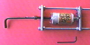 | Years ago I purchased a full blown drill press, mainly to press on pinion gears. John
has come up with this very handy tool, at a MUCH lower price than a drill press.
The Pinion Gear Press can be ordered from New Creations R/C or direct from
John. You can reach John E. McCullough at 5020 Stockton Drive, Raleigh, NC 27600, phone: (919) 851-3538 or e-mail at:
jem11@mindspring.com |
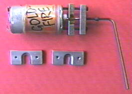 | If you need a pinion puller too, Kirk Massey, of
New Creations R/C, has an excellent one, also designed by John. It is shown here with the optional lower jaws for the AF 05-15
& AF 25-90. New Creations R/C can be reached at: P.O. Box 496, Willis, TX 77378 , or phone: (409) 856- 4630.
The New Creations R/C WEBsite is located at: http://www.newcreations-rc.com/
(Sponsor of the Mid-America Fun Flies) |
Return to "What's In This Issue?"
Tiger Shark Prototype Flies by Ken Myers
May 10, 1997 - Northville Township, MI
The proto type of the Tiger Shark flew at about 7:00 P.M. Weather
was clear, about 500F and winds just under 10mph from the northwest.
The first flight was approximately 5 - 6 minutes of "feeling out the plane."
The takeoff was easy and power was reduced immediately after breaking ground. There was a short period of time where a
little left aileron trim and a touch of down trim were adjusted in. After takeoff, the plane was never again flown at full throttle.
Both the aileron throw and elevator throw were more than I liked, so the plane was brought in for an easy landing. No surprises.
The Sanyo 1700SCRC 10 cell pack was recharged in just over 12 minutes at 5 amps, which indicated that it was just over half
depleted, which is what I anticipated. The elevator throw was adjusted and a second flight was made. There were no problems,
except the aileron throw and elevator throw were still too great for my poor vision and growing darkness. The second landing was
as easy as the first. The plane slows down nicely and it's easy to put onto the field.
It was a very successful evening. The plane is light in the air, easy to control and
thus far has shown no bad tendencies. The ground handling is positive and easy, although the takeoff run is very short.
It appears to meet the design criteria of a ten minute flight with good aerobatic
potential.
Vital Stats:
Model: Tiger Shark
Type: low-wing sport electric
Designer: Ken Myers
Finished Weight: 58.6 oz. - 3lbs. 10.6 oz.
Airfoil: NACA 2412
Wing Span: 55 in.
Wing Area: 486 sq.in. - 3.375 sq.ft.
Wing Loading: 17.36 oz./sq.ft.
Fuselage length: 37 in.
Fuselage height at l.e. of wing: 4 in.
Fuselage width at l.e. of wing: 2.875 in.
Controls: rudder, elevator, ailerons, throttle
Radio: Hitec Focus 4 FM Tx & 535 Micro receiver, Rx battery 270mah Sanyo, 2 Hitec HS-101 & 1 Futaba S-30
Electronic Speed Controller (ESC): Jomar SC-4
Connectors: Sermos
Fuse: auto spade type - 25 amp
Motor: Astro Flight 05 geared
Battery: 10 Sanyo 1700SCRC
Prop: Zinger 10x6
Prop Loading: 107.44 oz./sq.ft. of prop area
Prop shaft to ground clearance: 6.25 in.
Initial Static RPM: 8,700
Initial Static Motor Volts: 10.6
Initial Static Amps: 26.8
Initial motor input power: 284 watts
Initial input watts per pound: 77.56 watt/lb.
Initial output power: 219 watts (approx.)
Initial output watts per pound: 59.8 watts/lb.
Return to "What's In This Issue?"
Upcoming Events:
August 3, RESCHEDULED - Capital Area Soaring Associations Annual Summer
Sizzler Electric Fun Fly, Rockville MD --- For more information contact Roy Smith: 301-279-2966
or email at mailto:SuzGoose@AOL.com
We have rescheduled the annual CASA electric fun fly we held on April 13, It was a wash-out
or rather a wind-out. We had a very nice turn out with folks from several different states, but
the wind was 20+ and very gusty.
Thanks, Charles French
Aug. 2 - 5 - AMA Headquarters, Muncie, IN Doug Ward, R.D. #1, Box 189. Irwin, PA 15642 (412) 446-5891or email Doug at
DWard79207@aol.com
Aug. 16 NOTE: ORIGINAL POST OF AUG. 17 WAS WRONG Fourth Annual SEFLI Mountain Fly-Inn, in East Dover, VT. Electric
fun fly and Class A/B sailplane, Class A old-timer, 1/2a Sailplane and 1/2a texaco Old
timer.. Hand lauched models only as there is no prepared runway (hay field). Contact Tom Hunt
516-981-0372 --- P.O. Box 1467, Lake Grove, N.Y. 11755-0867 or by E-mailing Tom Hunt at
THunt95147@aol.com
Aug. 16/17 Halton Hills, George Ball Memorial Electric Fun Fly, Ont. Geoff Miller (905) 454-5198
September 20 & 21 Queen City Airport, Allentown, PA: KRC - setup on the 19th. For more info e-mail Anthony Assetto at
102723.2566@compuserve.com
October 4 & 5 11th Annual DEAF Fly-In, Dallas R/C Club Field in Seagoville Greg Judy (817) 468-0962 or email
75267.224@compuserve.com
October 17, 18 & 19 Gulf States Electric Fly-In hosted by the Ozone R/C Club --- for more info: Paul Perret, 1780 Prytania Street,
New Orleans, LA 70130 (504) 524-3442 or email at PaulCPerret@worldnet.att.net or Ben
Mathews, 101 Mulberry Drive Metairie, LA 70005 (504) 833-5589 or email at
Benmat@worldnet.att.net
Return to "What's In This Issue?"
Next Meeting: Thursday, July 3, 1997, 7:30 or ASAP - Rushton Road Flying Field, South
Lyon, MI, between 8 & 9 Mile Roads
To Reach Ken Myers, you can land mail to the address at the top of the page. My E-mail address is:
KMyersEFO@aol.com EFO WEBsite: http://members.aol.com/KMyersEFO/
Return to "What's In This Issue?"
