 |
Flying High With Electric Power!
The Ampeer ON-LINE!
Fly the Future - Fly Electric! |
Site Table of Contents
| President: | Vice-President: | Secretary/Treasurer: |
| Ken Myers | Richard Utkan | Rick Sawicki |
| 5256 Wildcat | 240 Cabinet | 5089 Ledgewood Ct. W. |
| Croswell, MI 48422 | Milford, MI 48381 | Commerce Twp., MI 48382 |
| (810) 679-3238 | (248) 685-1705 | 248.685.7056 |
 | ||
| Board of Directors: | Board of Directors: | Ampeer Editor |
| David Stacer | Jack Lemon | Ken Myers |
| 16575 Brookland Blvd. | 8908 Sandy Ridge Dr. | 5256 Wildcat Rd. |
| Northville, MI 48167 | White Lake, MI 48386 | Croswell, MI 48422 |
| 248.924.2324 | 248.698.4683 | 810.679.3238 |
| Mailed Ampeer subscriptions are $10 a year US & Canada and $17 a year world wide. FREE on-line! | ||
| The Next Meeting: Date: Sat. & Sun., July 8 & 9 Time: 9:00 a.m. Place Midwest RC Society 5 Mi. Rd. Flying Field - the Mid-Am | ||
|
John Worth has a brand-new INTRO TO INDOOR RC GUIDE. It is free online and can be found at this URL: www.cloud9rc.com/indoorflying.asp.
Bob Benjamin Inducted Into the AMA Hall of Fame I just received word that the designer of the TigerCat, TigerKitten, Miss Kitty and Baby Kitty has been inducted in the AMA Hall of Fame. Bob took up the electric flight challenge in 1988. In 1990 he began to participate in R/C scale competition against glow-powered planes. In 1998 he earned the position of 1st Alternate to the F4C team with his Astro 90 powered 1/4 scale 1941 Taylorcraft. In 1999 he became the first modeler to compete at TOP GUN using electric power. He took the Taylorcraft to TOP GUN in 2000 and placed Fifth in the Designer Scale Class. This was the first time an electric powered airplane finished "in the money" (top 5) at TOP GUN.
Upcoming Mid-America Electric Flies!
Registration open 9:00 Each Day
CD: Ken Myers kmyersefo@aol.com
CD: Keith Shaw (734) 973-6309 Pilot's Potluck Saturday Night
Low Cell Detect Circuit Two
This offering is an expansion of the June '06 Ampeer article entitled "Building the Low Cell Detect Circuit". That article - for advanced hobbyists - described a simple circuit assembly (LCDC) to be used in conjunction with Li-Po powered Electrics for the purpose of monitoring pack voltage cell-by-cell in flight. When the first cell within a pack declines to a predetermined ("detect") level, the LCDC acts to gradually retard throttle to preclude that cell (and hence the pack as a whole) from being over discharged. In effect, the LCDC is a much better LVC (low voltage cutoff) than that found in the typical ESC. Graphical representation of its operation can be found in the April '06 Ampeer.
PARTS LIST Use the Parts List from reference article, except:
TESTING LCDC2 As before, it is strongly advised NOT to connect your newly assembled circuit to a Li-Po "cold turkey", but rather first perform the testing below. The test setup described in June is still applicable, but the detail procedure has been simplified for version 2. (Use ONLY the original test regimen for the original LCDC design ONLY!) DO USE the June article as general guideline, proceed as below: RESISTANCE CHECKS The first tests are performed with the ohmmeter function of your DMM. For each step below, the ohmmeter is to be connected twice Đ i.e., do each test with normal and then reversed meter leads. (This means there are two resistance measurements for each step below.) Use the appropriate ohmmeter range to test wires:
Use highest ohmmeter range to test wires:
Any discrepancies must be resolved before proceeding. VOLTAGE CHECKS Be sure you understand and assemble the "Source" as described in June. Use the appropriate DC voltage range of your DMM to perform the following tests. (1) Connect Source (+) to a 10 K resistor and the other resistor lead to wire 1. Connect Source (-) to wire 3. First note the actual 18V Source voltage and then measure the voltage from wire 3 to wire 1. This voltage is to be 28% +/- 3% of the Source value. Perform ALL following tests expeditiously because the current demand on the 18-volt battery is fairly high. (Read through it all first so you know "where you're going"!) (2) Connect the Source (+) lead to a 100 Ohm resistor and the other resistor lead to wire D. Connect Source (-) to wire A. Measure the voltage across the 100 Ohm resistor - it should be between 1.7 and 2 volts. The actual value will be influenced some by your choice of Ra and the condition of your 18 volt battery under this load. Any discrepancies must be resolved before proceeding, but if all is OK, immediately proceed to ---- SIMULATED PERFORMANCE TESTS The "signal" test procedure for LCDC2 is the same as described in June (except the pot is changed). Of course, the "detect" voltage levels now should be the values you chose with resistor Ra. Don't forget the temporary test clip lead jumper from wire 3 to wire A (some did!)
ACTUAL PERFORMANCE TESTS If all above is OK, then be sure to read and follow the June text as you proceed to deploy your LCDC2 - including the "final test" part. Please write if you have any questions. Some earlier readers have done this, are now successfully flying LCDCs, and their Li-Po batteries are MUCH happier - they say!
Final hints. Be sure to disconnect the balance connectors (as you do the power connectors) from the Li-Po at end-of-flight. LCDC and LCDC2 work best for programmable throttle ranges between 1.1 mSec and 1.9 mSec. (Non-programmable Tx's normally fall within this range.) The tabulated V/C values are "nominal" and perfectly adequate - I have "the whole range" in use in my own planes. Be advised that ESC's differ somewhat in how they react to LCDC influence. Most I have are very smooth reacting. I have one that tends to "wobble" slightly (barely audible) when under final LCDC control. This may be more noticeable in gear drive systems.
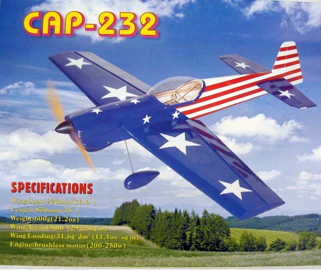
Bob CAP 232 ARTF Review
I've attached a review for my latest electric, A CAP 232.
Mike Southwood - UK |
|
Wing Span: 920mm - 36.6"
A small company called RCM Direct has started to import (Into England. KM) high quality ARTF models from China. I have had the pleasure of assembling three of these in the last few weeks. They are the, Spitfire, Extra 300 and the subject of the review, the CAP 232.
Servos:
Motor:
ESC:
Battery:
Radio:
THE MODEL comes in a good-sized box with the separate wing panels, fuselage and tail parts bagged. The cowl is a superb lightweight GRP moulding. Other parts such as fittings, wheels, nuts and bolts etc are bagged and taped securely. All components are of good quality. Some people might not like the turret fittings for one end of each control rod, but they do work.
ASSEMBLING: The instructions are very poor. They consist mostly of photographs, but do not make it clear that two servos are required for the wing. You need to have had some experience to build this one and the others from this supplier to realize that. The manual shows one central servo and torque rods, but the wing has holes for two servos and pull strings to get the servo wires through.
FUSELAGE: Again I used my little solder iron to cut out the servo holes and the fin and elevator slots. |
|
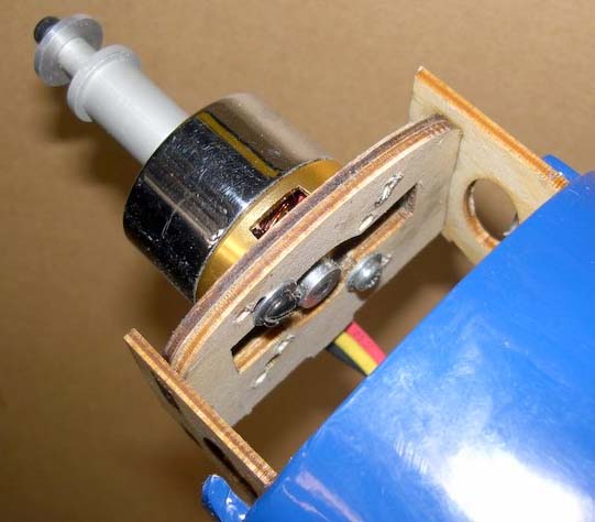
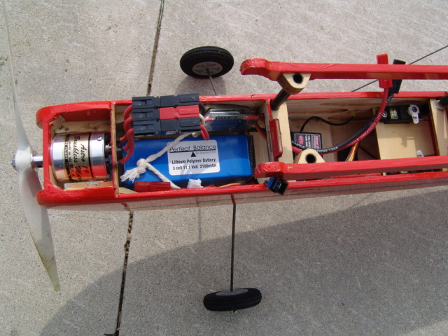
The motor mounting comes as laser cut plywood pieces or a square stick. The manual does not explain anything about this. If I used a motor with a gearbox and stick mount, it would be easy to use this and throw away the ply pieces. My motor is a rear mount type outrunner. It was best to assemble and glue the plywood mounting box. Nothing tells you which pieces to use or how to assemble them, but by trail and error it was achieved. One point to watch is that there is built in side thrust, so if you assemble the wrong parts on the side, you point left not right. The final result was very good and the cowl fit perfectly over the motor with just the right gap to the back of the spinner. Servos are fitted at the tail and again fitted the holes perfectly. I was slightly worried that the little Supertec Naro servos might not have enough power, but to use the 9-gram type would require opening up the holes and would add 8 grams extra weight in the tail. Wires again were extended. The fin and stabiliser were positioned. They fitted the machined slots perfectly and were glued with super glue (Cyno). The elevator joiner wire is best put in with the stabiliser. It can be inserted if you forget, but it may damage the slot. The elevator and rudder are fitted with furry plastic hinges, which went in perfectly and were secured with superglue (Cyno). Even the joiner holes were pre drilled. Don't forget to fit the skid to the rudder before gluing the hinges! The supplied canopy is trimmed and painted, but is clear. Although it is nice looking through it at the superb laser cut formers etc, I decided that it would look better if it were painted black. I just sprayed the inside with black car paint. An undercarriage is supplied with lovely spats, but this was left off as I fly from grass and it would not last long. RADIO: The lightweight e-sky 6-channel receiver was fixed on a 1/16" hard balsa sheet with back-to-back tape glued across the fuselage. All connections to the motor, ESC and battery were soldered and heat shrunk to 3mm gold plated tubular connectors. I followed my normal pattern by fitting the male connectors upstream so that the fully covered battery connectors could not short out, or the output from the ESC. A battery tray is provided, as is Velcro fastener tape. I glued the tray in the front of the fuselage with PVA. Then primed the tray surface with UHU as there is no large flat surface, it being cut out with lightening holes. FINAL ASSEMBLY: The holes are pre-drilled in the wing and were exactly positioned to enter the pre-fitted captive nuts. The fit of the wing was excellent. All that remained was to position the battery pack and set the balance by moving the pack. FLYING:
|

|
CONCLUSION: This is a superbly designed and manufactured 36.6" span CAP 232 ARTF. It is certainly not a beginner's model, as it requires quite a few minor changes and some careful work to enlarge servo holes to get 9-gram versions in. The finished model looks superb, both on the ground and in the air. The chosen motor gives about 850 grams thrust as used with a 3 cell 1600mAh Li-Poly, so we have more than 1 to 1 against the 728 grams of weight.
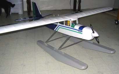
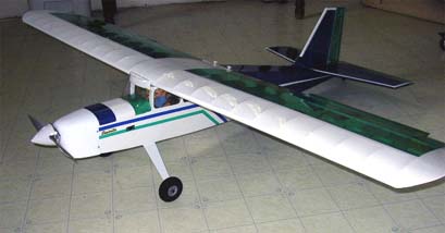
News from "Up North"
Ken, Greetings Ken and all those at the club.
|
|
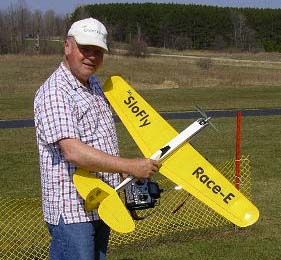
The final image is of Jim Maine with his plans built Race E. A very nice little plane and Jim did a great job building and covering it. The decals were made by his wife jean using commercial decal material. |
|
Correction to June LCDC Article The original versions (PDF & HTML) of the June 2006 Ampeer contained an error in a part number. Both versions now available online have been replaced with the part number corrected.
NEAT Fair Pilot Pre-Registration Opens
Well ladies and gentlemen; it's that time again.
Tom Hunt
Astro Brushless 19 Direct Drive Motor p/n 819-9T Review
|
|
Description: Bob Boucher sent an Astro Brushless 19 Direct Drive Motor (www.astroflight.com), here after referred to as the AF 19 Direct, for me to review after a couple of articles of secondhand experience appeared in recent Ampeers.
Flight Testing
How was my Cutie/AcroPro changed?
Procedure notes: I removed the prop adapter and did a drill press test. Then I ground a flat onto motor shaft for the prop shaft adapter set screw. I weighed the motor, including the leads and Zero Loss connector on a triple beam balance scale in grams. I weighed the prop adapter. Next "blue" thread lock was placed on prop adapter set screw and the adapter placed back onto shaft and the setscrew tightened. A Castle Creations Phoenix-45 ESC was used for the testing with the default settings. All of the props used for testing were balanced. I did three sets of tests in one day. I always tested from highest draw prop to lowest on same battery charge. I then recharged the battery and repeated the procedure two more times, allowing everything to cool down between the tests. The results were recorded and then entered into a spreadsheet. Test Series: Date: May 22, 2006
No Load test 1: Battery: 7-cell Panasonic 2000mAh
No Load test 2: Battery: 6-cell Sanyo RC 2000
All of the loaded tests used the same 10-cell Sanyo RC1700 NiCad battery. Three test series runs were made with five data point captures per run. Load 1 test: Prop: Mfg. Description APC 10x7E
Load 2 test: Prop: Mfg. Description APC 9x6E
Load 3 test: Prop: Mfg. Description APC 8x6E Weight: 12.2g Hub thickness: 8.8mm
Load 4 test: Prop: Mfg. Description Rev-Up 8x4
Conclusion: While this motor has similar specifications to some of the current crop of Asian outrunners, the AF 19 Direct has samarium cobalt magnets that are much less susceptible to heat damage than the neodym magnets used in the outrunners. It is well built and definitely worth considering over any of the outrunners in its class, and it is priced competitively. Addendum: Astro Flight/Bob Boucher has now changed the AF 19 Direct data on his Web site to reflect real world data. The heading over the prop data now reads "Measured Performance on X Volts" with the X Volts being 7.0, 10.5 and 14 to reflect performance with 2, 3 and 4 Li-Po cells in series. Check it out and notice how closely his data for the 8x6E on a 3S matches mine. |
To Reach Ken Myers, you can land mail to the address at the top of the page. My E-mail
address is:
KMyersEFO@mac.com
EFO WEBsite: http://members.aol.com/KMyersEFO/