 |
Flying High With Electric Power!
The Ampeer ON-LINE!
Fly the Future - Fly Electric! |
Site Table of Contents
| President: | Vice-President: | Secretary/Treasurer: |
| Ken Myers | Richard Utkan | Rick Sawicki |
| 5256 Wildcat | 240 Cabinet | 5089 Ledgewood Ct. W. |
| Croswell, MI 48422 | Milford, MI 48381 | Commerce Twp., MI 48382 |
| (810) 679-3238 | (248) 685-1705 | 248.685.7056 |
 | ||
| Board of Directors: | Board of Directors: | Ampeer Editor |
| David Stacer | Jack Lemon | Ken Myers |
| 16575 Brookland Blvd. | 8908 Sandy Ridge Dr. | 5256 Wildcat Rd. |
| Northville, MI 48167 | White Lake, MI 48386 | Croswell, MI 48422 |
| 248.924.2324 | 248.698.4683 | 810.679.3238 |
| Mailed Ampeer subscriptions are $10 a year US & Canada and $17 a year world wide. FREE on-line! | ||
| The Next Meeting: Date: Saturday, June 24 Time: 10:00 a.m. Place Midwest RC Society 5 Mi. Rd. Flying Field | ||
|
In the April issue of the Ampeer I asked for reader input on this topic. Like most polls, the input was light but I feel valuable. Thanks to those who took the time to write. We all appreciate it.
Group 1:
Group 2:
Group 3
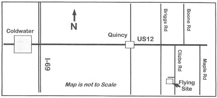
Upcoming SuperFly V On November 11 and 12 the all-electric fun fly event known as SuperFly V takes place in Las Vegas, Nevada. They schedule it every year in November because it is the off-season in other parts of the country, but it is still nice weather in Las Vegas. It is also the Veterans' Day Holiday so Friday makes it a three-day weekend and a good travel day.
The Keith Shaw Birthday Electric Fly
|
|
Dave Grife CD, 517-279-8445. Building the Low Cell Detect Circuit
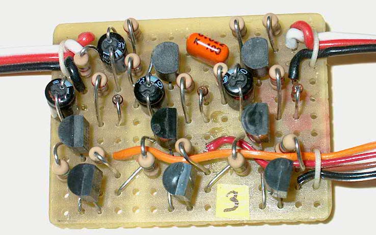
The (Li-Poly) Low Cell Detect Circuit (LCDC) for non-optically coupled electronic speed controls (ESCs) is an accessory that inserts in the Rx-ESC cable and also connects to the balancing connector of a Li-Po battery. It senses when any cell in a pack drops near the 3-volt level and reacts by automatically retarding throttle signal. Please refer to the April '06 Ampeer for additional description. Note - the LCDC does NOT work with optically coupled (opto) ESCs.
The LCDC, being connected to a Li-Po pack balance ("taps") connector, compares individual cell voltages to precision references (IC1 - IC3) and associated transistor (Q1 - Q3) emitter diode forward voltages. With cell voltages above about 3.15 volts, the transistors are ON making diodes D1 - D3 reverse biased and "out of the picture". This allows Rx throttle signal to pass undisturbed through the circuitry associated with Q4 and Q5 and on to the ESC. However, when any cell begins to drop below this voltage level, that associated reference IC and transistor begin to turn OFF. The corresponding diode then begins to conduct. This loads the collector signal of Q4 resulting in the gradual narrowing of throttle control pulses to effect throttle retardation. This in turn reduces current demand on the pack and preempts further decline of the cell that caused this circuit action in the first place. Thus the LCDC prevents the "low cell" from destroying itself through continued discharge by automatically reducing motor power. This action is gradual but obvious and permit�s a go-round or two for safe landing. A full pre-installation electrical test of the LCDC is not doable without some extraordinary equipment. But connecting a newly assembled circuit to the power system "cold turkey" is risky and unwise - remember - this is a Li-Po pack you are connecting to. The best compromise is a detail checkout using a digital multi-meter (DMM) and some simple test accessories.
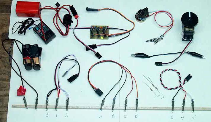
Also needed are one each 2.2K, 10K, and 22K ohm resistors, a 500 ohm variable resistor ("pot"), mini clip test leads for your meter, an aileron extension cable cut in half with corresponding wire ends soldered together and to mini clips (making a "Y" cable of sorts), a single-ended servo wire with mini clips, one clip lead jumper wire, and a battery-side balance connector with leads and clips. Note the wire / clip designations that follow correspond to the schematic and board assembly connection designators. It is convenient to clip all leads to a balsa stick to keep everything conveniently and safely in place on the test bench. |
|
The first tests are performed with the ohmmeter function of your DMM. For each step below, the ohmmeter is to be connected twice - i.e., do each test with normal and then reversed meter leads. (This means there are two resistance measurements for each step below.)
VOLTAGE CHECKS Use the appropriate DC voltage range of your DMM to perform the following tests. (1) Connect Source (+) to a 10 K resistor and the other resistor lead to wire 1. Connect Source (-) to wire 3. First note the actual 18V Source voltage and then measure the voltage from wire 3 to wire 1. This voltage is to be 28% +/- 3% of the Source value. (2) Connect a 22K resistor to the Source (+). Connect the other resistor lead to wire B and Source (-) to wire A. Measure the voltage between wires A and B to be 2.75 to 2.95 volts. (3) Move the Source (+) to wire C and Source (-) wire B. The voltage on each placement pair should be between 2.75 and 2.95 volts. Repeat for wires C and D. All three readings should be nearly equal to each other. (4) Reverse the Source polarity in the above process by connecting the 22K resistor to wire A (then B, then C) and the battery negative lead to wire B (then C, then D). Voltage readings should fall between 1.0 and 1.15 volts and be nearly equal to each other. (5) Repeat (only) step (3) substituting a 2.2K resistor for the 22K one. The corresponding voltmeter readings should be between 4.0 and 4.5 volts with the value between the A and B wires being about 5% higher than the voltages between the B - C and C - D combinations. This is actually a subtle check on circuit behavior so do note that approximate 5% distinction. Any discrepancies must be resolved before proceeding. It is time to do a real signal test of the LCDC. This test will use an actual transmitter and receiver (Tx / Rx) throttle signal and servo as test equipment.
Bob | ||||||||||||||||||||||||
PC Layout: LCDCBrd2.pdf
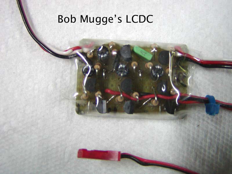
The LCDC: An Endorsement
| |||||||||||||||||||||||||||||||||||||||||||||||||||||||||||||||||||||||||||||||||||||||
|
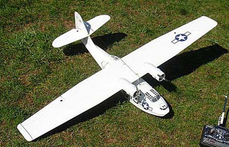
Bob Kopski's article in the April 2006 Ampeer about the LCDC sounded like just what I needed for in-flight protection of my Li-Po cells! Some recent announcements for low voltage cutoff circuits didn't sound good, as total cutoff of the motors for my 13-pound B-17, just to save the batteries, didn't sound very practical. Bob's LCDC, which retards the throttle and allows you to retain full control of your plane, with plenty of time to get down safely, sounded great!
I ran two motors in my B-17 that normally run off one 3S3P pack. I used an Astro Flight Whattmeter to monitor the pack volts and amps, and three separate DVMs (digital voltmeters) to monitor each of the three series cells. I connected an oscilloscope to look at the throttle signal. The pack was not quite at full charge, but that didn't matter since I was interested more in what the low end would do. At the start of the test, full throttle gave Whattmeter readings of 10.0V and 39.3A. Throttle pulse width was approximately 1.9 ms. At mid-discharge (about 5 minutes, down to 9.3V and 25A total current) it became obvious from the scope that the pulse width had begun to decrease (1.7-1.8 ms), and the lowest of the three cell DVMs had reached 3.13V, which is where the LCDC should begin to slow things down.
April EFO Flying Meeting
Ken, Congrats on a successful maiden flight on your Fusion!! It looked and flew very well. I may have something in that 'performance league' in the next few months. 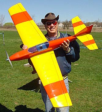 It is a joy to fly. While it was extremely windy, as you said, it flew very well. More on it in future Ampeers. KM Anyway, I watched you guys having a lot of fun. It seemed a bit windy for my lightweights so I opted to observe. 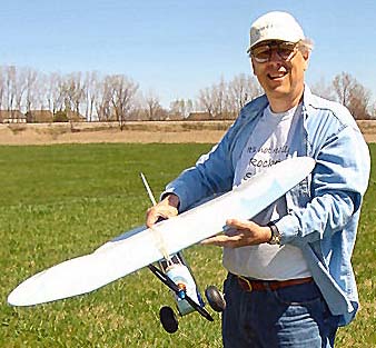
Roger and His Lazy Bee - Note the AF05 Geared Old AF brushed Motors are still excellent power I think Roger had the most flights with his Lazy Bee. I think he got in about 5 flights and had a ball doing rudder-rolls in all that wind. 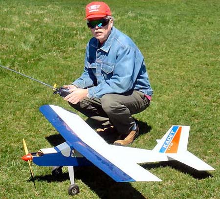
Richard Utkan & His LT-25 - good flier in the wind! Rich had a successful maiden with his new SIG LT-25.
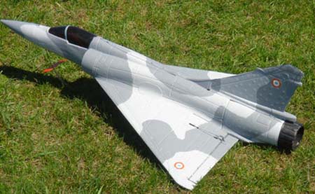
Tom's Mirage really moved out in the wind Too bad Toms' plane suffered a mid-air with the other EDF plane.
All of the photos were taken by Jim. Thank you Jim!
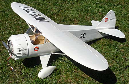
Jim Young had new Li-Po batteries to try out in his Hughes & Mr. Mulligan 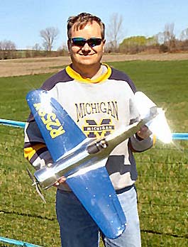
Jim Young also flew and took photos and video for his report on the Ezone of Sig's new E-Force Built-Up 3D ARF (www.rcgroups.com/links/index.php?id=4995) Keith Shaw's Stomo
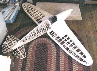
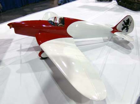
Keith Shaw entered his new Stomo into the Toledo RC Expo static contest. It is an electrically powered sport model inspired by an eligent, efficient homebuilt designed by Hans Moeller in 1930's Germany. Wing Span: 85 inches Wing area: 1050 sq.in.
 Clarification on the Astro Flight Direct Drive 19 Brushless
I had a phone call from Bob Boucher after the article using his motor as an example appeared in the May Ampeer. We discussed a lot of things and I have noted a few of Bob's comments here. I tried to take good notes during the conversation but much of the following is paraphrased and not direct quotes from Bob. The numbered items are Bob's comments.
I would like to thank Bob for taking the time to call and explain Astro Flight's procedures. As I stated in the May issue of the Ampeer, put this motor into a 15 to 19 glow airframe on a 3S Li-Po pack and have a ball! Upcoming Mid-America Electric Flies!
|
To Reach Ken Myers, you can land mail to the address at the top of the page. My E-mail
address is:
KMyersEFO@mac.com
EFO WEBsite: http://members.aol.com/KMyersEFO/