|
Ampeer Paper Subscriber Reminder
When subscribing to or renewing the paper version of the Ampeer, please make the check payable to Ken Myers. We do not have a DBA for the Ampeer or EFO. Thanks, Ken
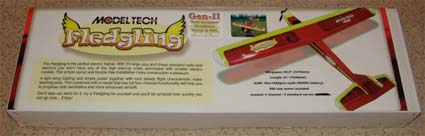
Model Tech Fledgling Gen-II With BL Motor & ESC No. 123506
By Ken Myers
Preface:
In the May 2009 Ampeer I speculated that this plane might make a good "4-channel" trainer using a 3S "A123" 2300mAh pack. While the plane is marketed for use with a 3S1P 2100mAh Li-Po pack, I noted that I wanted the faster charging time and safety of a 3S1P "A123" 2300mAh pack for use with my student pilots.
I was wrong when I speculated that it was a "high-wing" trainer. It is actually a "shoulder-wing" design.
Unfortunately, when I received the almost ready to fly (ARF) kit, even though the shipping box and the box containing the kit had no damage, the wings were damaged from poor construction and design.
Since I wanted to get this plane into the air as soon as possible, I elected to "fix" the wing panels myself, without contacting Hobby People for a replace set of wing panels.
Aircraft Type: Shoulder-Wing 4-Function Trainer
Airfoil: flat bottom
Appropriate Flying Area w/3S "A123" 2300mAh pack: RC club field
Airframe Out of box weights and my modified weights:
Horizontal stab & Elevator: 26.95g/0.95 oz. - "Monokote" hinged 33.1g/1.17 oz. (+3.15g/0.11 oz.)
Vertical stab & Rudder: 14.2g/0.5 oz. - "Monokote" hinged 16.8g/0.6 oz. (+0.09 oz.)
Left wing panel: 103g/3.63 oz. - fixed 114.5g/4.04 oz. (+0.41 oz.)
Right wing panel: 93.2g/3.29 oz. - fixed 105.4g/3.72 oz. (+0.43 oz.)
Fuselage without motor: 185.1g/6.53 oz.
Rudder/Elevator Pushrods: 10.3g/0.36 oz.
Aileron Pushrods: 1.6g/0.06 oz.
4-clevis & ~0.5" long fuel line: 3.1g/0.11 oz.
2 control horns & screws: 3g/0.11 oz.
Misc. screws & washers: 2.5g/0.09 oz.
Hook & Loop fastener: 1.9g/0.07 oz.
Stuff in Wood parts bag: 14.3g/0.5 oz.
Landing gear & Stuff in stuff in LG parts bag: 28.6g/1 oz. - 1/8" piano wire LG & Stuff in LG bag 40g/1.41 oz. (+0.4 oz.)
Supplied Main Wheels 50mm/1.97": 9.3g/0.33 oz. - Dave Brown 2-1/2" Lite Flite Wheels 62mm/2.44" 34.8g/1.23 oz. (+0.9 oz.)
Tail wheel, bracket & screws: 11g/0.39 oz. - new tail wheel assy. w/1/16" wire 11.3g/0.4 oz. (+0.1 oz.)
Trimmed decal: 3.2g/0.11 oz. (note: I put decal on right wing panel for total wt. of 108.6g)
Completed airframe weight with my modifications: 20.5 oz.
Power System
Collet Type Prop Adapter (5mm x 8mm output shaft): 19.3g/0.68 oz.
Prop (10x5?) - not used: 16.4g/0.58 oz.
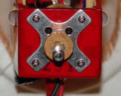
TowerPro 3015-7 Motor: 134g/4.73 oz.
"+" mount & 8 screws: 10g/0.35 oz.
Measured Kv: 1065
Measured Motor Outside Diameter: 37mm/1.46"
Measured Motor Length: 33.8mm/1.33"
Shaft length: 60mm/2.36"
Shaft diameter: 5mm/0.2"
Radio
Supplied ESC: 49g/1.73 oz. (not used)
ESC Castle Creations' Thunderbird 54 w/2 full size APP and 3 cut down APP connectors & hook & loop fastener: ~1.5 oz.
1 Hitec HS-81 w/hardware (ailerons): ~0.7 oz.
2 Hitec HS-80 w/hardware (rudder & elevator): ~1.4 oz.
Receiver Spektrum AR500 w/Velcro: ~0.3 oz.
Total On-board Radio components: ~3.9 oz.
Measured Specifications:
Fuselage length: 37.5"
Rudder width: 1.625"
Total length not including length of prop adapter: 38.125" (Supplied info: 41")
Wingspan: 56.125" (Supplied info: 55.5")
Root chord: 9.625"
Tip chord before rounded tip starts: 7.5625"
Tip area: ~14 sq.in. x 2
Wing panel span 25.6875" root to beginning of tip
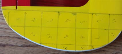
Wing Area: 469.5 sq.in (Supplied info: 495 sq.in.)
(Calculated Mean Aerodynamic Chord (MAC) 8.6")
CG: 25% MAC 2.15" or 2-3/16"
CG: 30% MAC 2.58" or 2-9/16"
CG: 33% MAC 2.87" or 2-7/8"
With 1.5" of ground clearance, up to a 13" diameter prop can be used with either the stock wheels or the Dave Brown 2-1/2" wheels.
The Fledgling was ordered from Hobby People on Sunday, April 19 and arrived via FedEx, in great shape, on Friday, April 24. The kit plus shipping was $158.98, which included the reasonable $8.99 for shipping.
The kit box was removed from the shipping box on the morning of Saturday, April 25.
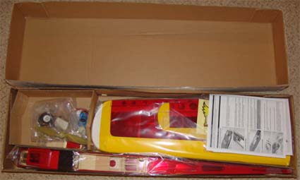
At first glance the contents appeared to be well packaged.
Next, I carefully removed the contents, examined, weighed and measured them.
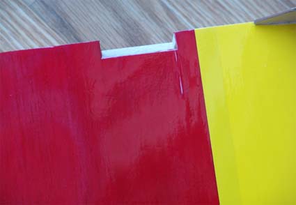
I was extremely disappointed to find that, even though there was no outer damage to the shipping box or kit box, the right wing panel bottom sheeting had split and torn the covering out through the third bay from the root.
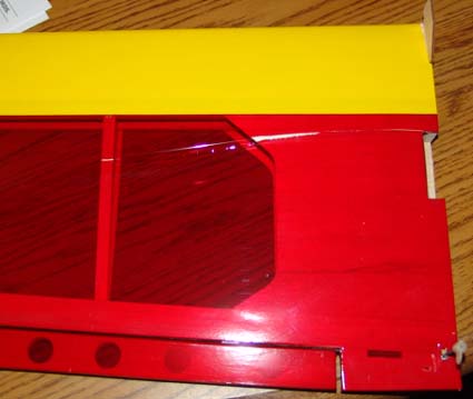
Closer examination revealed that the left wing panel bottom sheeting had also split near the cutout for the servo but had not yet torn the covering too far.
While checking the weights of the components, the TowerPro 3015-7 outrunner motor (list price $23.95US) was removed from the fuselage and the Kv was determined to be about 1065 rpm/v using the drill press method.
TowerPro 3015-7 at Hobby City
I carefully measured, re-measured and calculated the wing area. There is a 25.5 sq.in. difference between the actual measured area and the area stated in the supplied documentation.
Since I wanted to use a 3S "A123" 2300mAh pack, I trial fitted a pack into the fuselage and found that it was wide enough to hold 2 of these cells side-by-side.
The supplied electronic speed control (ESC) is a TowerPro L40-acro 40Amp Brushless Speed Controller, list price $22.75US.
This ESC at Hobby City
This ESC is supposedly set up to run a 3S Li-Po. The only way to program the ESC is with the Towerpro N20 and L40 Programming Box available from Hobby City/Hobby King, list price $3.95US.
Programming Box at Hobby City
Hopefully the supplied ESC is programmed to work with a 3S Li-Po pack for someone who chooses to use a 3S Li-Po battery.
According to the instructions supplied with the ESC, even with the Programming Box, I could see no way to set the cutoff voltage to what I needed for a 3S "A123" 2300mAh pack. I chose to use a Castle Creations' Thunderbird 54 for this project.
Next, I "fixed" the wing panels using thin Jet CA to glue the sheeting breaks in both panels near the servo cutouts. I used Top Flite Econokote red to repair the lower wing panels. I also elected to use "Monokote" type hinges, made from Econokote, instead of the supplied CA type. That type of hinging is just a personal preference.
The last thing I managed to get done on the first day was to epoxy the wing panels together.
It made for a long day.
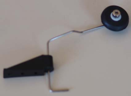
That evening, while looking at the thread about the Fledgling on RC Groups, I read about the tail wheel assembly problem.
www.rcgroups.com/forums/showpost.php?p=11296152&postcount=13
Sure enough the tail wheel assembly doesn't fit!
I started the second day by gluing the plywood wing hold down reinforcement to the wing. Once I glued it in place, I decided to glue the tail wheel landing gear block onto the aft of the fuselage for the tail wheel bracket. Wrong! I should have cut the block down by 1/4" first. Instead, I removed the supplied tail wheel wire and bent a new tail wheel wire from 1/16" piano wire.
Next I "Monokote" hinged the vertical stab and rudder and the horizontal stab and elevator.
The horizontal stab/elevator was measured to see that it was square and horizontal to the wing. The covering was removed from the horizontal stab where it fits into the fuselage and the assembly 30-minute epoxied into place, again checking to make sure that everything was square and horizontal.
After my unsuccessful trip to a local hobby shop to get a Hitec HS-82MG servo, I glued on the vertical stab/rudder assembly. (RANT - I mention this trip only because I have had terrible, terrible luck with local hobby shops. On no, zero, none, of the occasions that I have visited any of the local hobby shops in the past year, have they had what I wanted! Nothing I have gone after is strange or extremely electric specific in any way; thin CA that is NOT Bob Smith, APC E props, Hitec HS-225 servos, Great Planes control horns, Thunderbird 54 ESC, etc. Sorry, just a little rant!)
I remounted the motor.
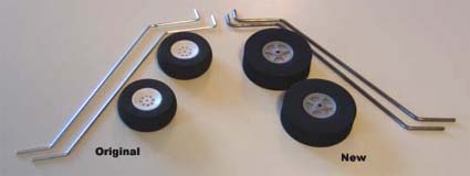
While checking to see how I could use 1/8" piano for wire for the landing gear, I found another problem with the kit. The supplied landing gear is "too loose" in the landing gear slot. Actually, two 1/8" (0.125") wires side by side fit perfectly in the slot. The supplied gear appears to by 2.7mm or 0.10236" and made out of a shinny metal.
The third day started by verifying the Mean Aerodynamic Chord (MAC), because of what I read the previous evening in the manual regarding the center of gravity (CG). The MAC is 8.6".
The manual states, "FOR TEST-FLYING WE SUGGEST YOU START WITH THE C/G AT 2-3/4" (70mm), then move it farther back as you become familiar with the flying characteristics of the airplane. It is not recommended that the C/G be located any farther back that 3" (76mm)." I can see why!
Next, using the supplied main landing gear wire as a pattern, I used my K&S wire bender to bend new main gear using 1/8" piano wire. I found that the supplied wheel collars are 1/8" and can be used. The collars would be a "sloppy" fit on the supplied landing gear wires. Flats were ground on the axles for the wheel collar set screws and the main landing gear attached to the airframe using the screws and straps provided in the kit.
The tail wheel bracket was screwed to the triangle block at the rear of the fuselage.
I replaced the stock wheels with Dave Brown Products 2-1/2" Lite Flite Wheels for better roll out on a grass field.
I leveled the fuselage and measured to check for prop clearance. Using the stock wheels or the 2.5" Dave Brown wheels, the plane can clear a 13" diameter prop with about 1.5" of ground clearance or more.
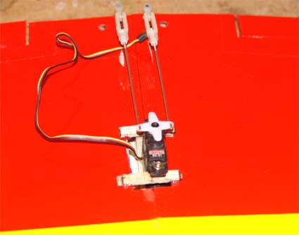
The fourth day began with the frustrating task of installing the rudder and elevator control horns. Unlike the photo in the manual, the supplied control horns use three screws to hold the control horn onto the surface, not two. Aligning three holes through a surface is much more difficult than aligning two holes. There was no mention of pre-threading the holes in the control horn back plates, which is essential to successfully installing the control horns.
I created the next problem. Unfortunately, I missed the fact that the elevator pushrod is 22-3/4" long and the rudder pushrod is 23" long. I reversed them! The way I had installed them, they did not align with each other at the servo location shown in the manual. It pays to pay attention to the manual, sometimes! It wasn't a huge problem for me, since I was "moving" the servos anyway.
While threading a clevis onto the very thin pushrod wire, I noticed that the clevis is easily "stripped". The pushrod wire is very small in diameter and the threads are very fine. When the clevis strips it can just slide up and down the wire and won't "catch" on the small, fine threads.
I knew the plane was going to be somewhat tail heavy, from my observations and also from a note on RC Groups. www.rcgroups.com/forums/showpost.php?p=11891736&postcount=40
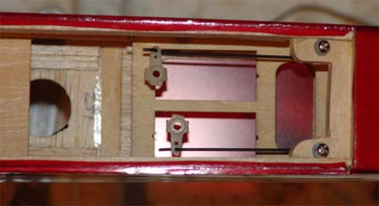
I removed part of the installed rudder/elevator servo tray to get the rudder and elevator servos forward and aligned with the pushrods, the way I had them installed.
I had no "standard" servos, and didn't want to purchase them for this plane. Standard servos would have also exacerbated the tail-heavy balance problem.
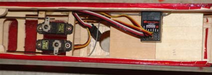
I used Hitec HS-80s on the rudder and elevator and a Hitec HS-81 on the ailerons. To allow for my misalignment of the rudder and elevator pushrods, I aligned the 1/4" square plywood crosspieces so that the pushrods aligned correctly. First I epoxied in the rear cross member and let the epoxy cure.
Next I measured, cut from 1/8" plywood and epoxied the 1/8"x1/4"x1-1/4" crosspieces for the aileron servo.
While the epoxy cured, I removed the supplied motor connectors and installed Anderson Power Pole (APP) connectors with about 1/2 the housing cut away to shorten them. I also installed APP connectors to the battery and motor connections the Thunderbird 54. Using the Castle Link, I set the cutoff voltage to 6 volts for use with a 3S "A123" 2300mAh battery. I use a timer to time the flights and don't want the low voltage cutoff (LVC) kicking in. An appropriate LVC should be used whenever a Li-Po pack is used!
The front rudder/elevator servo crosspiece was epoxied into place.
To allow the epoxy time to cure, the new AR500 receiver was bound to the DX5e transmitter. That is a very simple process.
The motor was run on a couple of different props, just to get an idea of what props to try for the real motor data collection for the TowerPro 3015-7 motor.
On the morning of the fifth day, the servos were screwed down, surfaces set to neutral, pushrods connected and servo horn screws installed.
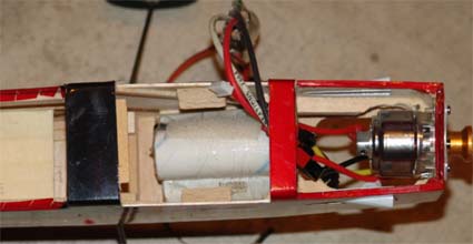
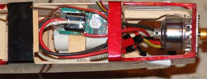
The hatch for the battery area was cut from the fuselage. The 3S "A123" 2300mAh pack was installed using a hook & loop fastener and a plywood crosspiece to retain the battery and provide a platform for the ESC to be hook & loop fastened to. The hatch was completed by adding balsa "side stoppers", a front tongue, and a 1/8" plywood crosspiece was glued to the window area of the fuselage for the hatch screw.
Props were selected and balanced for the motor testing. The motor was prepared for its test by using spray adhesive to secure a strip of white paper around the bell and then a piece of blue striping tape for the tach to read for the no load tests. A 2S and a 3S "A123" were charged for the no load tests.
Spray adhesive was used to attach 150-grit sandpaper to the prop adapter. The sandpaper keeps the prop from slipping when it is tightened.
The motor/prop testing was completed and the data entered into Drive Calculator. The motor was uploaded to the Drive Calculator site.
www.drivecalc.de
On day 6 the battery was fixed into place. The Thunderbird 54 was hook & loop fastened to the battery holder crosspiece. The "new" top hatch was screwed on, as well as the provided bottom hatch.
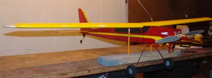
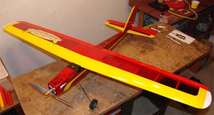
Photos were taken of the tools and materials used to complete the plane, the finished plane, the plane being balanced and the parts in the original kit not used.
The ready to fly (RTF) weight of the wing with a Hitec HS-81 installed is 257.7g/9.09 oz. The RTF weight of the fuselage is 885g/31.2 oz. The total RTF weight is 1142.7g/40.3 oz. with an APC 13x8E prop installed on the motor.
The CWL (wing cube loading) is 6.85 oz./cu.ft. That is just a little lighter than I had hoped for. The area wing loading is 12.36 oz./sq.ft.
Using Drive Calculator and my spreadsheet data (fledgling.xls), I decided to use an APC 12x8E prop on the maiden.
With the battery moved to the rear of the battery compartment, which had been created above the landing gear, and the APC 12x8E prop mounted on the motor, the CG was 2.5" from the leading edge of the wing. That position is just a little less than 30% of the MAC, and is a good starting point.
Tools and materials that I used:
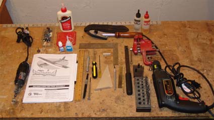
Dremel rotary tool w/cutoff wheel, sanding disk, grinding disk and small saw blade
Power drill w/1/16" and 5/64" bits
Pin vise with 1/16" bit
Loctite, Jet thin CA, Titebond, 30-Minute Epoxy, Vice, K&S Wire bender, 12" ruler, metal triangle, small metal square, various screwdrivers, X-acto knife with #11 blade, single edge razor blades, X-acto saw blade, covering iron, heat gun, soldering iron, needle nose pliers, 36" metal rule, some 150-grit sandpaper, marking pen, construction manual, prop balancer, CG/balancer (homemade)
Red Top Flite Econocote to repair the damaged wing and "Monokote" type hinges.
3M General Purpose 45 Spray Adhesive & 150-grit sandpaper
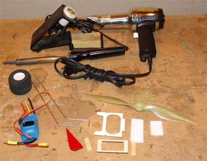
The parts from the kit that I did not use are shown in the foreground.
Recommended "Fixes" from Front to Back
1.) Prop adapter - Affix 150-grit or 100-grit sandpaper to the smooth front of the prop adapter. Use spray adhesive on the smooth front of the adapter and the back of the sandpaper. Press the sandpaper and adapter together. Allow drying. Trim the sandpaper with a single edge razor blade to match the round adapter and trim out the center hole.
2.) Balance problem with Li-Po battery and standard servos - Remove the motor and "+" mount, reverse the motor shaft, attach the "+" mount to the motor, attach the "+" mount with the motor attached to the front of plane's firewall, and run the motor leads under the firewall to the ESC. The motor is now positioned on the outside, front of the plane.
3.) Landing gear problem - A.) Replace the supplied wire main landing gear with 1/8" piano wire using the supplied gear as the pattern for the landing gear legs. A wire bender will make the job much easier. Drill the landing gear blocks to accept the 1/8" wire landing gear legs. Replace the supplied wheels with at least 2-1/2" wheels. Create "flats" on the landing gear axles for the wheel collar set screws. Use a file or a Dremel rotary tool with a grinding wheel to make the "flats". Use thread lock, such as Loctite, on the landing wheel collar set screws.
B.) To use the supplied landing gear, use silicone fuel line to take up the slack per this article:
www.rcuniverse.com/magazine/article_display.cfm?article_id=825
4.) Tail wheel mounting bracket problem - A razor saw blade can be used to cut 1/4" from the wooden tail wheel mounting bracket block on the edge that mounts to the fuselage. The cut should be level so that the tail wheel mounting bracket sits level on the back end of the fuselage. Sand level if necessary. The tail wheel bracket will also have to be trimmed to fit the "new" mounting block.
Flying
Two test flights were made on Saturday, May 2. The day was not ideal for test flying a new plane. The winds were relatively high, much higher than would be acceptable for flying a student pilot. The winds were 10 mph to 20 mph and gusting. They were pretty much closer to 10 mph, but the gusts were into the 20's for sure.
The Fledgling flew just fine. Of course the take off into the wind was really quick, especially at full throttle with almost 300 watts in. Very little trimming was needed. I was very happy with the way the plane flew for a shoulder-wing, flat-bottom airfoil trainer in the wind.
I am looking forward to using this "trainer" and buddy box with my students.
An Unexpected Bonus:
The Spektrum DX5e and Parkzone (ZX10) 5 Channel FM 72 MHz are buddy box compatible!
Return to "What's In This Issue"
Put This One On Your Event Schedule!
Keith Shaw Birthday Party Electric Fly-In
From Dave Grife grifesd@yahoo.com
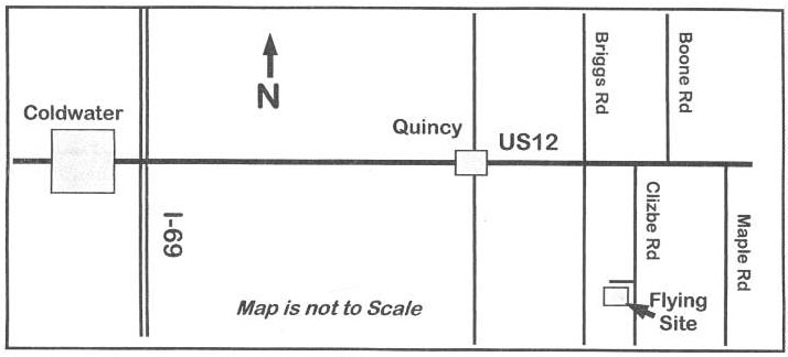
The Balsa Butchers will once again be hosting the "Keith Shaw Birthday Party Electric Fly-In" at their field near Coldwater, MI. The event will take place on June 6 and 7, 2009.
Contest Director: Dave Grife - E-mail:
grifesd@yahoo.com or Phone: 517.279.8445
Please e-mail or call with any questions
The Flying Field will be open Friday, June 5 for early arrivals
Saturday, June 6, hours are from 9 a.m. 'til 5 p.m.
Sunday, June 7, hours are form 9 a.m. 'til 3 p.m.
Landing Fee is $10 for the weekend.
Directions: Quincy is approximately 4.5 miles east of I-69. Clizbe Road is approximately 1.6 miles east of Quincy. The Flying site is approximately 1.5 miles south of US-12 on the west side of Clizbe Road. |