|
EFO Meeting WEDNESDAY 7
The first flying meeting is scheduled. See ya then.
Outrunner Motor Nomenclature Drives Us Nuts
From Brian Amato Traverse City, MI
Questions and Comments via emails
BA: Just read the entire "Everything you ever wanted to know about Electric Flying" and was hoping to find an explanation of what the number designations mean between one motor and another. Either I missed it or there is none.
Further reading tells me there IS no standard designation between motor manufacturers in how they describe their motors.
KM: You are absolutely correct. That is why I've chosen to add the exterior dimensions, Kv and motor weight to outrunner motor names in the Ampeer. The Ampeer designation uses the diameter in mm followed by the total can length in mm then a dash followed by the Kv (RPM/v) and then the weight in grams. Using the Kv and the weight, similar outrunner motors can be found.
BA: Most consistent seems to be the stator diameter and then the stator thickness, but that can just as easily mean the can diameter and can length with the next distributor.
KM: The reason I chose the exterior dimensions, Kv and weight in grams for the nomenclature in the Ampeer is that it is the easiest for any hobbyist to verify. The term 'watts', when used generically by most RC writers, is almost always referring to watts in at the ESC, which are easily measured by a power meter. You may have noticed that for a long time I used watts in with an underline so that hopefully the readers of the Ampeer coalesce the idea in their minds.
BA: Can you send me some place to get a better understanding?
KM: I see from your follow-up email that you found the Motors section of the "Electric Power Basics" article.
I believe that cleared up some of the 'confusion' in this area for you.
BA: And when it's all said and done, though, it still doesn't tell us just how much "oomph" that motor is going to have and which one we should pick for our super whiz bang park flyer or aerobatic beauty.
KM: Actually, the weight and Kv do indicate how much oomph a motor might be able to produce, and more importantly, how the oomph may be applied. The motor should not be thought of a single entity. It is only one part of a total system. The mission of the airframe determines the prop, which is the load for the motor. The motor supplies the mechanical energy to the prop. The ESC rations the electrical energy from the battery, the energy source, based on the demands of the pilot, much like the carburetor of an engine. The battery contains the amount of stored onboard energy like a fuel tank, but it has limits as to how much energy it can supply at a given time and over time.
BA: I just can't believe that we've gone from the days of "wet" engines where a .35 was a .35 was a .35 to the wonderful world of electric flying where a C2826 has nothing in common with a SII-3008 next to a 2789.
Let's see some tables that tell me how much thrust this thing has.
KM: A .35 was never a .35 in the glow world. We only perceive that it was. A ringed .35 was/is an entirely different engine from a Schnuerle ported .36. They use different props and are used differently for different missions. Glow and gas engines have a very narrow useful maximum power range. The narrow maximum power range limits the props that may be used on a given engine to a very narrow range as well.
Your statement about thrust is not about motors. Thrust is about props. Motors, along with 'help' from the ESC and battery, supply the mechanical energy to turn the prop. The term thrust also indicates that you are into ducted fans, 3D type flying or helicopters. For planes that 'fly on the wing', like sport and sport scale planes, the flight speed to stall speed ratio is more important than 'raw thrust' numbers for a prop at a given RPM. The flight speed to stall speed ratio is determined by the design of the airframe, including such things as wing area, ready to fly weight and aerodynamic 'cleanliness' as well as its mission. A typical powered thermal sailplane is very different in design and mission from a racing plane or a scale biplane.
The weight of the motor does indicate something about its potential when used with an appropriate ESC and battery, but the prop is the final determinate.
I don't know of any plane designed for electric power, plans, kit, ARF, etc., that doesn't have a recommendation for a power system provided by the supplier. It's simple. Follow the recommendations until you learn more about power systems. Don't make it harder than it is.
I do feel your frustration, but you are confusing the great flexibility of electric power systems with the inherent inflexibility of glow engines.
A Follow-up Email
Brian sent a follow-up email. He wondered why we couldn't use horsepower ratings like a pick-up truck or motor found on a table saw.
Hi Brian,
While your analogies using vehicle horsepower and table saw electric motor horsepower are interesting, they are not valid when applied to the electric motors used with our power systems. Engines are designed to use a certain type of fuel such as gasoline, diesel, alcohol, hydrogen, etc. These fuels have a pretty much 'fixed' amount of energy that they can deliver to the engine at maximum horsepower. Electric motors in tools and appliances are designed to either use AC, with a fairly stable fixed voltage, or DC with a fixed voltage by the number of cells and types of cells in the battery. Overall, the engine or motor is purpose designed for the fuel or a reasonably stable voltage source.
We may use a given brushless outrunner with quite a wide range of voltages by varying the cell count and chemistry of battery. This changes the possible maximum work potential of the motor to the potential of the energy source, the battery. The mission or type of airframe determines how we put any given motor and battery combination to work with a certain type of prop. We may also choose not to use the motor and/or battery to its maximum potential in a given application.
The manufactures' or suppliers' literature may indicate the maximum amps and/or wattage input, but there are a myriad of practical uses for the motor with less than maximum potential power.
Here are the power specifications for the Scorpion SII-3020-780 (3846-780, 166g). This motor was chosen because Innov8tive Designs has prepared a power source and prop table for it, which can be used as a reference guide without referring to one of the motor/battery/prop calculator computer programs such as Drive Calculator.
Max Continuous Current: 40 Amps
Max Continuous Power: 800 Watts (in KM)
800 watts in / 40 Amps = 20 volts
The motor current capability is based on the many things, but one of the predominant factors is the wire size of the winds and their current carrying capacity. The voltage supplied to the motor has a practical limit based on cell count and the chemistry of the battery.
The nominal voltage of the battery may be used to estimate the practical number of cells for a given chemistry.
Li-Poly nominal voltage 3.7 � 20v / 3.7v = 5.41 cells - practical limit 5 cells
"A123" 2300mAh nominal voltage 3.3 � 20v / 3.3v = 6.06 - practical limit 6 cells
NiCad or NiMH nominal voltage 1.2 � 20v / 1.2v = 16.67 - practical limit 16 cells
Li-Poly practical watts at 40 amps * 18.5v = 740 watts in
"A123" 2300mAh practical watts at 40 amps * 19.8v = 792 watts in
NiCad or NiMH practical watts at 40 amps * 19.2 = 768 watts in
The power source-prop table suggests that an APC 11x5.5E is the largest APC prop (the brand that I have prop constants for) that can be used with a 5S Li-Poly. The stated 663.8 watts in is less than the 740 watts in suggested previously for a 5S Li-Poly battery. A good motor/battery/prop calculator might indicate possible use of a different prop if the maximum is desired. For this explanation, the APC 11x5.5E will be used. The table shows that with 663.8 watts in the prop is turning 11,375 RPM and the PROP is producing 2771g of thrust with a pitch speed of 59.2 mph.
The table does not indicate the efficiency at this power level. One way to calculate the power out is to use one of the many computer motor/battery/prop analysis programs or to use something known as prop constants. The prop constants for the APC 11x5.5E are Factor 0.2143764 and Exponent 3.227256. The formula is (11,375 RPM/1000)^ 3.227256 times 0.2143764 = 548.3 watts out or about 0.74 shp.
Efficiency = 548.3 / 663.8 = 82.6%
The referenced table also suggests that an APC 9x9E requires approximately the same power in when used with a 5S Li-Poly. At 662.4 watts in the prop is turning 11,400 RPM and producing 1699g of thrust with a pitch speed of 97.2 mph.
The prop constants for the APC 9x9E are Factor 0.1569973 and Exponent 3.381076. (11,400 RPM/1000)^ 3.381076 * 0.1569973 = 588 watts out or about 0.78 shp.
Efficiency = 588 / 662.4 = 88.7%
There are many variables involved and the real world numbers will not match the math perfectly, but if you want to use 'horsepower', as way to grapple with this in your mind, you could call the motor, at this power level, a 3/4 shp motor.
In reality, the types of airframes and missions that these 3/4 shp systems would be used in could be entirely different. While not the only types of airframes and missions for possible use, the motor combined with a 5S Li-Poly and using the APC 11x5.5E could be used in a sport plane type with a ready to fly (RTF) weight of up to about 6.5 lb. (104 oz.) at 100 watts in per pound of ready to fly (RTF) weight. The same motor and number of Li-Poly cells, when used with the APC 9x9E, could be used in a very clean racing design with a RTF weight of maybe 3.3 pounds (52.8 oz.). That would be about 200 watts in per pound.
The table suggests that an APC 11x8.5E has the highest input watts for this motor when used with a 4S Li-Poly and with the amp draw at 40 or less. With 500.8 watts in the prop is turning 9,000 RPM and producing 2005g of thrust with a pitch speed of 72.4 mph.
The prop constants for the APC 11x8.5E are Factor 0.2399295 and Exponent 3.391173. (9,000 RPM/1000)^ 3.391173 * 0.2399295 = 413.1 watts out or about 0.55 shp.
Efficiency = 413.1 / 500.8 = 82.4%
The table also suggests that an APC 10x10E requires just slightly less power in when used with a 4S Li-Poly. With 479.8 watts in the prop is turning 9,025 RPM and the prop is producing 1440g of thrust with a pitch speed of 85.5 mph.
The prop constants for the APC 10x10E are Factor 0.6800008 and Exponent 2.9. (9,025 RPM/1000)^ 2.9 * 0.6800008 = 401.1 watts out or about 0.54 shp.
Efficiency = 401.1 / 479.8 = 83.6%
The numbers indicates that with a 4S Li-Poly this is a 1/2 shp system. Is the motor 3/4 shp like in the 5S example or 1/2 shp like in the 4S? The answer is neither and both. It is the whole system, not the motor, which defines the final useful power.
Again, the now 1/2 shp systems could be used differently. While not the only types of airframes and missions for possible use, the motor and 4S Li-Poly, when using the APC 11x8.5E could be used in a sport plane type with a ready to fly (RTF) weight of up to about 5 lb. (80 oz.). When used with the APC 10x10E it could be used in a racing design with a RTF weight of maybe 2.4 pounds (38.4 oz.).
Finally, the table suggests that an APC 13x10E has the highest input watts while not exceeding 40 amps when used with a 3S Li-Poly. With 401.0 watts in the prop is turning 6350 RPM and producing 1611g of thrust with a pitch speed of 60.1 mph.
The prop constants for the APC 13x10E are Factor 1.223826 and Exponent 3.0. (6350 RPM/1000)^ 3.0 * 1.223826 = 313.4 watts out or about 0.42 shp.
Efficiency = 313.4 / 401.0 = 78.2%
The table also suggests that an APC 14x8.5E requires slightly less power in when used with a 3S Li-Poly. With 378.3 watts in the prop is turning 6,400 RPM and the prop is producing 2117g of thrust with a pitch speed of 51.5 mph.
The prop constants for the APC 14x8.5E are Factor 0.9888079 and Exponent 3.074625. (6,400 RPM/1000)^ 3.074625* 0.9888079 = 297.7 watts out or about 0.40 shp.
Efficiency = 297.7 / 378.3 = 78.7%
The way the now 2/5 shp systems could be used might be different. The motor and 3S Li-Poly with the APC 13x10E could be used in a low-wing sport or sport scale plane type with a ready to fly (RTF) weight of up to about 4 lb. (64 oz.). The same motor and a 3S Li-Poly when used with an APC 14x8.5E, with its higher thrust and lower pitch speed, might better be used in an airframe that has a bit more drag, possibly a biplane with a RTF weight of about the same 4 pounds.
Trying to think of 'a motor' in a single given way is quite futile. The whole power system must be considered. There is just no other way to do it. Think system.
There are some rules of thumb and general rules that aid in thinking about electric power.
The bigger/heavier the motor is, the more real world work it is able to do without being 'overworked'. In the case of the popular outrunner motors, the heavier the motor, the greater the power potential, all other aspects of the motor's production being equal. Again, all other things being equal, the heavier the motor is the more efficient it will be over its lighter brother.
The weight of an outrunner can be used to identify its possible potential and use.
For burst flying planes (3D types, warm & hot-liner gliders, old-timers or any type of plane flown with short bursts of maximum power over the flight duration) and for racing planes, where winning is all, the potential maximum use, without destruction of the motor, is the weight in grams times 4.5 or maybe even up to 5.
There are several sheets in the Excel spreadsheet workbook. Look on the sheet named 'outrun'. The watts in per gram of motor weight column notes the ones that exceed 3 watts in per gram of motor weight with a red background and white text. You can note their values and the types of planes and see where I got the 4.5 from, as well as the types of planes that I have identified here as burst planes.
For most of the rest of the prop driven planes using outrunners, it is the motor weight in grams times 3, which is 3 watts in per gram of motor weight for the maximum.
Both the 4.5 and 3.0 multipliers are maximums for relatively safe and long lasting operation using the modes of operation described.
For the Scorpion SII-3020-780 weighing 166g, used in a burst application, that would be 166 * 4.5 or 747 watts in.
The potential of that same motor, for longevity's sake, in a fly on the wing application would be 166 * 3 or 498 watts in.
On a personal note, almost all of my motors are used at about 2 watts in per gram of motor weight. I would tend to use a 166g outrunner at about 332 watts in (166g * 2) up to maybe 400 watts in (400 / 166 = 2.4 watts in per gram of motor weight).
Some manufacturers and suppliers, like Scorpion, also provide the same motor with different Kv numbers. The SII-3020 series are found at http://www.innov8tivedesigns.com/index.php?cPath=21_25_80&osCsid=f5804f37226137356734f6518c0734ba.
They are -
SII-3020-780 12 Turn Delta wind, Motor Wire 11-Strand 0.25mm, 40 amps, 800 watts in
SII-3020-890 10 Turn Delta wind, Motor Wire 14-Strand 0.25mm, 45 amps, 780 watts in
SII-3020-1110 8 Turn Delta wind, Motor Wire 17-Strand 0.25mm, 60 amps, 840 watts in
For a higher Kv there are fewer turns of thicker wire. The thicker the wire, the more current it can carry. This is shown well by the amps noted for each Kv. As a side note, there appears to be an anomaly in the watts in. The watts in for the 890Kv and 780Kv appear to be switched.
With all of the variables involved in selecting the whole power system, many people find that using a power system calculating program speeds the process of selecting a specific power system that meets their goals based on the mission of the airframe. Is it as simple as purchasing a vehicle with the power needed and suitability for the job or even a table saw that provides the power and longevity for the job? No. Can a reasonable selection be made using a power system calculation program as an aid in selecting a power system? Yes, but it does take some effort and some knowledge on the user's part.
Is there a simpler way to select a power system? As I've stated before, "I don't know of any plane designed for electric power, plans, kit, ARF, etc., that doesn't have a recommendation for a power system provided by the supplier. It's simple. Follow the recommendations until you learn more about power systems.
Don't make it harder than it is.
I hope this helps more than it confuses,
Ken
Another Follow-up from Brian
I just loaded the free trial of MotoCalc
.
Holy Toledo!!!! What an amazing piece of work and they say they update it constantly.
Where has this been all my life :)
Brian
Return to "What's In This Issue"
The March EFO Meeting
The monthly EFO meeting was held at Ken's house in Walled Lake on Wednesday, March 9.
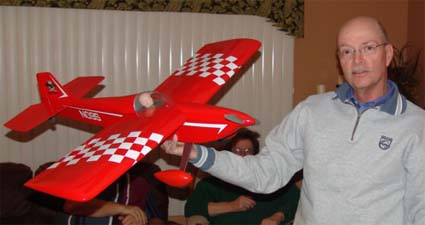
Denny Sumner lead off the evening describing his new Mark Rittinger redesign of Ken Willard's Top Dawg sport plane. Denny has a complete build thread on this little beauty on RC Groups.
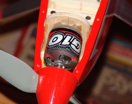
It is superbly built and has some really nice features built in, including the wing attachment sans the original rubber bands. The motor is one of the new Turnigy G10s.
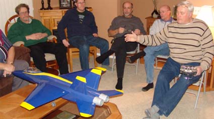
Hank Wildman brought back his HET F/A-18 Hornet Blue Angels ARF. It is now completed, and NOT EASILY. Everything about this ARF was a problem to solve.
Hank fired up the ducted fan. 2100 watts in can really blow around the dining room drapes! It should be a real mover!
Jim Young brought along is Howard Ike. It uses the power system and electronics from the E-flite UMX Beast. Jim has a full build thread on RC Groups.
Kits should be available by the time you read this. Check Jim's site at www.tnjmodels.rchomepage.com
Ken invited Lynn Morgan of the Midwest RC Society to come and speak to the EFO members about his excellent charging set-up. His set-up includes an e Station BC8DX Dual Charger, CellPro 10S, and two 350 watt, 120vac to 12VDC switching power supplies all in a "used" JR transmitter case. He uses a Honda EU1000i Generator to power the system at the field. It weighs only 29 lb., runs about 8 hours on a tank of fuel and super, super, super quiet.
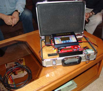
Lynn ran us through the numbers regarding his set-up and it appears that the set-up is just right for charging four 5000mAh Li-Polly packs at the same time at the field.

Lynn Morgan, second from right, shares info while EFO members follow along on his prepared handout.
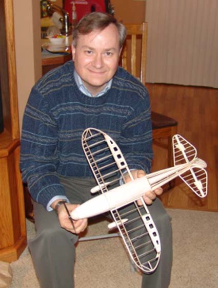
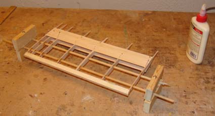
Ken Myers brought the members up to date on his AntonovAn-2 project.
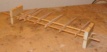
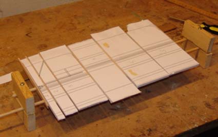
He'd mocked up the horizontal stabilizer using the technique he learned from Larry Sribnick. Larry used the same technique on his X-250. The wooden dowels will be carbon fiber on the actual model. The rib spacing and alignment were completed using Foamboard spacers.
The horizontal stabilizer and elevator were completed as one unit.
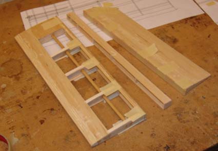
The assembly was cut on a Dremel table saw to separate the horizontal stabilizer from the elevator and the built up trailing and leading edges were added.
The stabilizer tips were built up in layers and then glued on the horizontal stabilizer and elevator.
A mock-up of the control line elevator horn was also made to check the clearances.
The tail strut was fabricated and the attachment points, and how to be able to move the attachment points were also figured out.
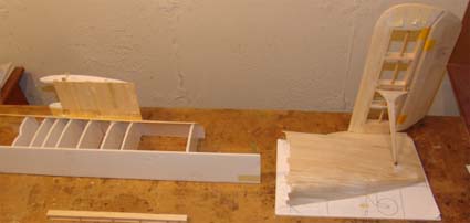
The photo shows the two mockup areas and wing strut and attachment point.
As usual it was a great meeting. We have all been looking forward to this year's flying season.
Return to "What's In This Issue"
Another Stearman
From Neil Johnson via email

Ken,
I have been building a 51" wingspan Stearman replica of the Navy one I soloed in. That was 01/10/1947. I will not have it finished in time for the Toledo show.
Return to "What's In This Issue"
Put This One On Your Event Schedule!
Keith Shaw Birthday Party Electric Fly-In
From Dave Grife grifesd@yahoo.com
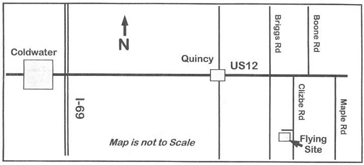
The Balsa Butchers will once host the "Keith Shaw Birthday Party Electric Fly-In" at their field near Coldwater, MI. This is the 10th Anniversary of this event. The event will take place on June 4 and 5, 2011.
Contest Director: Dave Grife - E-mail:
grifesd@yahoo.com or Phone: 517.279.8445
Please e-mail or call with any questions
The Flying Field will be open Friday, June 3 for early arrivals
Saturday, June 4, hours are from 9 a.m. 'til 5 p.m.
Sunday, June 5, hours are form 9 a.m. 'til 3 p.m.
Landing Fee is $10 for the weekend.
Directions: Quincy is approximately 4.5 miles east of I-69. Clizbe Road is approximately 1.6 miles east of Quincy. The Flying site is approximately 1.5 miles south of US-12 on the west side of Clizbe Road.
|