Ken Myers Change of ADDERESS!
Ken Myers
1911 Bradshaw Ct.
Walled Lake, MI 48390
Phone: 248-669-8124
Ampeer Paper Subscriber Reminder
When subscribing to or renewing the paper version of the Ampeer, please make the check payable to Ken Myers. We do not have a DBA for the Ampeer or EFO. Thanks, Ken
More On Selecting a Brushless Outrunner for a Sport or Sport Scale Project Using M1 Cells
By Ken Myers - October 2007
Last month I give a fairly detailed account of one way to select a brushless outrunner for Sport and Sport Scale projects using M1 (A123 Systems) cells.
All motors and cells can be used in a myriad of ways, and no one way is more correct than another as long as it works.
To simplify the process, I have chosen to use the M1 cells in the 100 watts in per cell range. The M1 cells can certainly be used at much higher and somewhat lower watts in per cell quite effectively. Personally, I have found that using them in the 35-amp draw area, they give me the flight time and power I desire for very good performance.
I have now created a few tables that will allow the average modeler to create these same types of planes. The tables make selecting the appropriate components easier.
Later, I will demonstrate how I used the tables to select the components for my latest project, a 40-size glow conversion.
Table 1 shows the anticipated battery weight including balance plugs, power leads and connectors, shrink-wrap or equivalent tape and Velcro for two-cell through 10-cell packs of M1 cells.
View Table 1
Tables 2 and 2a show the airframe selection numbers. As always, there are a lot of exceptions, but in general, these numbers work relatively well for prop driven aircraft.
The Maximum Completed Airframe (MCA) weight includes everything that is not part of the onboard radio system and its installation weights and the motor/battery components and their installation weights.
View Tables 2 & 2a
The suggested wing area range, as noted last month, is based on typical cubic wing loadings for these types of aircraft. Both somewhat larger and smaller areas may also be used successfully.
Using the Tables
Last month I gave several possible examples for a 5S M1 pack:
ElectroFlying Fusion kit, 569 sq.in.
Great Planes Dazzler 40 kit, 578 sq.in.
Sig Somethin' Extra kit, 614 sq.in.
Sig Four-Star 40 Kit, 604 sq.in.
Great Planes Super Sportster 40 MkII ARF, 555 sq.in.
Sig Four Star 40 ARF (Red or Yellow), 604 sq.in.
According to Table 1, all of the examples have the appropriate wing area for a 5S M1 pack based system, but if the MCA weight exceeds 40.5 oz., then a 6S M1 pack based power system would be more appropriate. The MCA weight is the primary determinate in selecting the most appropriate power system with the wing area being a secondary consideration.
The Power System
Table 3 shows the appropriate "typical" weight range of motors to provide a starting point in selecting a motor for a given sport/sport scale project.
View Table 3
Last month I noted that the manufacturers and suppliers do not do a very good job in helping us select an appropriate power system. Nothing has changed!
I have since devised a method to derive an approximate Kv range to match the pitch speed that I noted last month. I said, "In general, typical sport/sport scale planes have a pitch speed ((RPM * pitch in inches)/1056) between 50 mph and 70 mph." It should be noted that the smaller planes use pitch speeds closer to 50 mph and the largest ones considered here, 70 mph. That is taken into account in the Kv recommendations.
I also noted that prop diameter could be selected based on prop disk loading. Table 4 shows what I feel are the appropriate prop diameter and Kv ranges for typical sport/sport scale planes for the number of M1 cells.
View Table 4
The actual pitch used will depend on the chosen prop diameter and generally falls between 60% and 80% of the prop diameter. Using the 5S pack power system as an example:
11*0.6 = 6.6 or from an 11x6 through
11*0.8 = 8.8 to 11x9
12*0.6 = 7.2 or from a 12x7 through
12*0.8 = 9.6 to 12x10
13*0.6 = 7.8 or from a 13x7 through
13*0.8 = 10.4 to 13x11
14*0.6 = 8.4 or from 14x8 through
14*0.8 = 11.2 to 14x12
These are not hard and fast numbers. For example, if the RPM is high enough to reach a pitch speed of 55 mph to 60 mph (typical for this size and weight plane) using an APC 13x6.5E, then it may be an acceptable prop to evaluate in the air.
The higher the Kv in a given range, the smaller the diameter the prop will have to be to pull only 35 amps.
It also may be necessary to use the next lower set of Kv numbers to get the larger props to only pull 35 amps. In this 5S example, it might be necessary to look at motors in the 490 to 620 Kv range instead of the recommended 600 to 790 Kv range.
Again, to keep things simple, I tend to use APC props only. They are not necessarily better in any given application, but it makes the prop selection a whole lot simpler for a given project. I do not use the slow fly (SF) props; as they are not appropriate for the aircraft mission, pitch speed and motor RPM. I do use the thin electric (E), sport and pattern props.
I have posted the tables and motor selection information to the EFO Web site. According to my research, here is a list of possible motors for use with the 5S M1 pack:
View 5S Motor Recommendations
Sources and Notes are posted with this information on the Web site page noted above. I have included my notes for the TowerPro 3520-7 and -6, as these motors are the ones on the list that I have, therefore I am quite sure about the reliability of the data.
The -6 would be used when a smaller prop diameter is necessary because of landing gear considerations. Drive calculator data, which I input myself, indicates a 12x6E @ 35 amps has a pitch speed of 53 mph and an 11x8E @ 37 amps has a pitch speed of 60 mph. A Jeti Spin 44-amp was used to gather the data and it was set to 0-deg timing.
The -7 would be used to create more &auot;pull" with less pitch speed when prop clearance allows. Drive Calculator suggests a 12x10E @ 38 amps with a pitch speed of 70 mph and a 13x8 sport or E @ 35 amps with a 57 mph pitch speed. My input numbers were based on a Welgard 65-amp ESC set to 1-deg of timing.
How To Put This All Into Practice
Dymond RC Flite 40 - Mini Review
By Ken Myers
(A Fully Detailed Review can be found on the RC Groups thread: www.rcgroups.com/forums/showthread.php?t=735972 KM)
Dymond RC Photo from their Web site
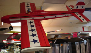
I received the plane on July 24 and took a photo of the parts in the box. The box the ARF (almost ready to fly) plane was packed in had no markings identifying the manufacturer. The kit/ARF contained no written materials. There was no way to identify what part of the world this ARF came from. My best guess would be southeast Asia or China.
I removed the parts from the plastic wrap, inspected and weighed them. All of the parts that might be used in the conversion came to a total of 1295.2g or 45.69 oz. The short write-up on the Dymond RC Web site noted that it could be set up as a tricycle gear or conventional gear plane. No provision was made for a tail wheel in the kit, so its weight is not included in the above total.
The wood seemed to be typical southeast Asian wood. That is, it is hard as a rock and heavy. The covering material seems to be some kind of heat shrink of fairly decent quality. The only things that needed some ironing were the blue star graphics. They were lifting from the white covering used for striping.
The wood parts for the kit appeared to be laser cut and the actual design of the framework, tail feathers and wing were quite good.
The airfoil is flat-bottomed with a bit of a resemblance to a Clark Y.
The measured wing area, including the plastic wing tips, was 646 sq.in. or 41.68 dm^2. The wingspan, including the tips, measured 58.125 in. or 1476.375 mm.
With a MCA weight not greater than 48.6 oz., as suggested by the parts weight, and a wing area of 646 sq.in., the sport plane fits easily into the 6S category.
Unfortunately, I had not come up with my new method of motor selection BEFORE actually purchasing the motor for this project. I had hoped that the plane would fall into the 5S category, as I already had the BP Hobbies/TowerPro 3520-7 I was planning to use for it. It didn't, but I still went ahead and used the TowerPro 3520-7 even though it has about the maximum Kv for 6S use.
This is the list of 6S motors that I should have been looking at:
View 6S Motor Recommendations
Again, sources and notes appear on the Web site at homepage.mac.com/kmyersefo/M1-outrunners.htm#TABLES.
I was able to use the 3520-7 on a 6S pack because when using an APC 12x7 sport prop, my recommended minimum diameter, I got; 17.45v, 35.0 amps, 9120 RPM, and 610.75 watts in yielding a pitch speed of 60 mph. The ESC was a Welgard 65-amp set to a timing advance of 1-deg.
I didn't care for the fiberglass fuselage top or the plastic wing tips. I modified the top to a turtledeck and hatch, thus giving the plane an open cockpit.
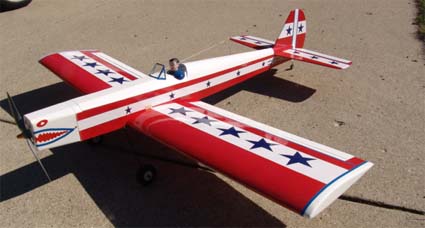
The finished plane specifications are:
Wingspan: 54 1/16"
Wing area: 615 sq.in.
Fuselage length: 51.25"
RTF Weight: 87.3 oz.
Wing Loading: 20.4 oz./sq.ft.
Cubic Wing Loading: 9.89 oz./cu.ft.
Initial Center of Gravity: ~3.5" from the wing's leading edge
Motor: TowerPro/BP Hobbies 3520-7
Prop: APC 12x7 sport
Prop disk loading: 111.15 oz./sq.ft of disk area
Battery: 6S1P M1 (A123 systems) harvested from DeWalt DC 9360 pack
Motor data using APC 12x7 sport prop
Maximum RPM: 9390
Static Maximum Amps: 35.8
Static Maximum Watts: 643
Watts in/lb.: ~117
Theoretical pitch speed: 62.2 mph
Theoretical Stall speed: 16.7 mph
Pitch speed to Stall speed ratio: 3.7:1
Onboard radio system:
ESC: Welgard 65-amp brushless
Sombra Labs Shadow 3 7-ch receiver
BP Hobbies 4-cell 700mAh NiMH pack
3 each Hitec HS-225BB
Transmitter:
Hitec Eclipse 7 7-ch
Flying the Dymond RC Flite 40
Saturday, August 18 was the perfect day to do the initial flights. Unfortunately, the Midwest 7 Mile Rd. field had not been mowed in quite a while and the runway grass was very, very long.
I took a flight with the Sonic 500 to check the grass and fly for the first time at this field.
I switched the transmitter to the Flite 40, set the timer for 5 minutes and double-checked all the controls. The takeoff was actually quite good and with just a little flying around it was easily trimmed with a couple of clicks of down elevator and left aileron. High and slow speed flight followed with a few loops and rolls to check the throw setup. Most important was the diving test to check the CG. It was just fine. The plane "feels" very well "balanced" in the air. The landing was a non-event.
The battery was charged and the timer was reset for 6 minutes for the second flight. I continued to feel out the plane and do several very basic maneuvers.
Sunday dawned with rain and temperatures in the mid-50s. Shortly after I arrived at the PMAC flying field for their e-meet, the rain abated to a light drizzle.
What the heck, I came to fly so I did.
Four more flights were put on the Flite 40. While the dive test on the previous day showed the CG to be properly placed, I could not get the plane to do a decent snap or spin. I think that part of the reason that it doesn't spin well is the very gentle flying characteristics of this type of moderately thick airfoil, but I'm going to move the CG back a little to see if that helps.
On Wednesday, August 22, I flew the plane to test using an APC 13x6.5E prop. It was 88-deg F at the Midwest field. I set the timer for two minutes, as I wanted to "split the flight" and took off using the APC 12x7 sport prop. After flying for a little over two minutes, I landed and changed props to the 13x6.5E. The takeoff was quite different, as the plane did not "rotate" as nicely as it had been with the heavier 12x7 sport prop. That lighter prop had made a difference in the handling. The plane noticeably had more "pull" in the vertical, but it was now a tad tail heavy. After flying around for two minutes I landed.
On landing, I felt the battery pack, and even in the 88-deg F heat, it felt just over ambient, and it has hardly any cooling. The motor felt quite warm, warmer than any time I had felt it before.
Sunday, August 26 was a beautiful day at the Midwest flying field. It was sunny with light winds and an ambient temperature of about 75-deg F. It was a great day for flying. The first flight went very well with no problems. It ended with an excellent landing and taxi back to the pits. The pack was recharged and the plane placed on the field for take off. The throttle was advanced and a click, click noise was heard, but no throttle. The throttle was chopped and tried again. There was a click, click then silence.
When the plane was brought back into the pit area and the hatch swung open, the smell of burned electronics permeated the air. The ESC had gone south. (It has since been replaced by BP Hobbies. Great Service! KM)
Who is this plane for?
This would be a very good low-wing trainer for someone who has soloed on a high wing trainer at a regular AMA flying field. It is not a park flyer. It is gentle and extremely easy to fly with no surprises for a pilot with good high-wing four-channel experience.
It is for someone who wants to create a "40-size" model on the cheap. The plane was $50 plus $19.99 for shipping. The DeWalt battery pack was $114.98 delivered with 4 cells left over for another project making the cost of the pack's cells $68.98 plus the cost of a balance plug, power wires and connectors, which means in the low $70 range. The BP Hobbies 3520-7 now list for $37.95 ( and can be purchased from United Hobbies in Hong Kong for $25.00US) and the BP Hobbies 70A ESC (equivalent to Welgard in this review) goes for $35.95 on August 26, 2007.
It's for someone who wants to have fun flying basic pattern type maneuvers with a gentle yet responsive plane.
I like it.
Return to "What's In This Issue"
Quick A123 Question
From Walt Thyng wthyng@earthlink.net
Question on the A123s: do you use the factory tabs for your 5 cells packs?
So far I've only created a 6-cell pack for the Flite 40 and a 2-cell pack for the EasyStar. Both use the factory tabs. KM
Attached is a picture of the naked Cobra. Hope to test her over Labor Day. It's sitting on a standard picnic table.
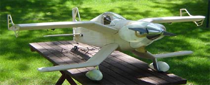
Can't wait to hear more on this one! KM
Return to "What's In This Issue"
An Experience with Spread Spectrum
From Dick Corby info@altacom.us
For about a year now I've been using Spread Spectrum radios. My first was the Spektrum DX-6 and it flew all my smaller planes extremely well. I didn't try it in anything large due to the specifications of 1000 ft. range. But in all uses for smaller planes, it was great.
I nearly bought a DX-7, but was clued in to the Xtreme Power Systems coming out with a very versatile SS system that could be mated to the Futaba 9C that I know and love. So I waited, and waited, and waited until the release after the Toledo Show. I got my module and first receiver in April, and haven't had a single problem that I didn't cause. You can't believe the improved connectivity between stick movement and plane response. It's almost as if you are in the plane and moving the surfaces. 16-bit data processing is so much faster than anything so far.
It is a great way for anyone that now has a radio, which uses a module for the RF. The XPS system is hands down more versatile than anything on the market at this time. And it, so far, is the only Bi-directional system, with two-way telemetry coming in the near future, and the ability to program the TX and RX from any computer. They have modules for nearly every type of radio, and more coming as they go down the road. Their biggest problem is they have trouble keeping up with the demand for their product.
www.xtremepowersystems.net/index.php
Spread Spectrum is the way to go no matter what system you look at. No pins, no conflicts with metal to metal, no chance for servo noise to cause interference. And there are some great low priced packages on the market now. Futaba's EX6 would get a newcomer into SS at about the same price as any low-end FM system.
Hope this may help someone that is considering Spread Spectrum. It's the wave of the future.
Dick Corby
Seattle RAMs
www.seattlerams.com
Return to "What's In This Issue"
Thoughts on Power System/Plane Matching
From Burkhard Erdlenbruch Burkhard@Erdlenbruch.de
Hi Ken,
Again your excellent measurements and explanations provoked my contradiction. A while ago, you (rightly) criticized ModelMotor's motor constant data. But in your latest article these data seem completely useless because they are valid only for a special ESC. But I think they are useful because they are valid for the recommended ESC setting (especially advancement) and that setting is possible with virtually any ESC (as long as they are adjustable).
The different impedances can be allowed for in the drive calculations. I do this by tweaking my Excel spreadsheet data using the ModelMotors measurements (their examples with different propellers and batteries). I think even DriveCalculator still uses the linear motor model characterized by the three well-known motor constants. (No, Drive Calculator does not use the three constant method. The original spreadsheet that DC is based on is still available for download. KM) They just have different data sets for each advancement setting. (Yes, there are different data sets for different timings. KM) At least a few cases I checked gave the same results using DC and my spreadsheets (up to 5% difference, likely the propeller coefficients).
But there was another idea new at least to me. I calculated the electric drives for two Reflex models, both an AXI 4120/14 but different batteries and props. The Ugly Stik and the Kwik-Fli are great with this drive! OK, I'm quite proud of these Reflex models and I love the vintage designs so I'm biased. But only now I realized that we are still in a similar situation as in the 1960s.
The R/C equipment was heavy, and also the glow engines were heavy and not that powerful. That's why the pattern models looked like they did. They were fast and flew patterns with an impetus. For landing, they almost needed a paved runway, and a tricycle landing gear was safer and easier than a tail dragger (and landing was in the maneuver schedule).
The 4120 with 4s2p 3000 battery (and ESC and prop) for the Ugly Stik weighs slightly more than an old .60 glow engine with tank etc. And the 4220 with 5s2p battery for the Kwik-Fli weighs slightly more than a later .60 with muffler. Instead the R/C equipment is lightweight today, so I expect the same overall weight. Both drives have not much more than half the performance of the glow engines but pull the models with at least as much authority and speed as the glow engines. This must be due to their higher efficiency, both motor and propeller, and because an electric motor better matches a propeller than a combustion engine. Anyway, the old models are great again, today with an electric drive.
Unfortunately, even LiPo capacity is still rather small and flight times short, whereas in the old times a bit more fuel in the tank was no problem. And there are so many drive configurations whereas there were only very few options in the 1960s. Therefore it's important to know exactly which drive fits a model and its purpose (though the Model Motors recommendations simply worked, I just checked them), at least if it's used to its limits. And therefore your work is so important.
I was reminded of your old equipment weight tables, and in a childish joy at my findings I just had to write this e-mail.
Best wishes,
Burkhard
P.S.: If you still have a current version of Reflex and when (if) you have some spare time in the winter, you might try the two Reflex models, especially with electric drive
(time.fh-augsburg.de/~erd/Modellflug/textDownloads.shtml).
Return to "What's In This Issue"
Electric Motors: Speed Type VS Brushless Outrunners
From Stuart Smith, Australia stuarttsmith@netspace.net.au
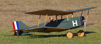
This will not be a comparison of all motors of these types, as I'm not setting myself up as an expert on electric motors only as it applied to one model, namely my scale SE5a.
The first SE5a was built from a pull out plan from a magazine at 27-inch span using a Speed 400. It flew but it was a dog. At this point I almost gave up.
I had the plan blown up to a 50-inch span (1270-mm). This model was fitted with a Speed 600 and a 3:1 belt drive gearbox driving a 12x8 prop. The power source was an eight-cell 3300 NiMH pack. Its total weight was 77 oz.
While it was flyable with this set up with any suggestion of a wind it was not possible.
As it was a very enjoyable model to fly, the next move was to go brushless. I did a little research using the MotoCalc Programme. (I can recommend this programme to anyone who is serious about electric flying, so long as it is used as a comparison). The following set up was settled on: a 900 Kv brushless out runner with operating efficiency between 20 to 30 amps, direct drive 10x7 prop, powered by two 2200 20C Li-Pos connected in parallel which equate to 88 amps of available power. There was a slight weight saving of 10 oz. with this set up.
The increase in power output was 2 to 3 times better than the Speed type motor. The first flight went well but the model flew at speed far greater than what could described as suitable for a model of an aircraft of this vintage. Limiting the maximum throttle setting via the end point adjustment on the Tx (just love these computer radios), the final setting draws about 21 amps (tested on the ground) which give about 15 minutes of continuous flying. Loops from level are now possible, with the ailerons on high rates a roll is possible, not perfect but properly similar to what the full size SE5 could perform.
The following are the Static Predictions from MotoCalc.
| Motor | HXT
35-48 | Graupner
Speed 600
Race 8.4V |
| Current (A) | 21.6 | 17.8 |
| Power Loss (W) | 41.2 | 71.7 |
| Motor/Gearbox Output (W) | 188.2 | 85.7 |
| Output Pwr Loading (W/lb) | 45.9 | 17.8 |
| Motor/Gearbox Eff. (%) | 82.0 | 54.4 |
| Shaft Efficiency (%) | 78.5 | 50.1 |
| Propeller RPM | 8563 | 4988 |
| Static Thrust (oz) | 32.1 | 25.5 |
| Pitch Speed (mph) | 56.8 | 37.8 |
| Stall Speed (mph) | 15 | 16 |
| Optimal Flight Speed (mph) | 23 | 24 |
| Throttle for Optimal (%) | 64 | 82 |
| Duration at Optimal (m:s) | 41:04 | 15:51 |
| Hands-off Speed (mph) | 25 | 27 |
| Throttle for Hands-off (%) | 67 | 87 |
| Duration Hands-off (m:s) | 37:33 | 15:12 |
| Best Rate of Climb (ft/min) | 516 | 155 |
| Rate of Sink (ft/min) | -281 | -304 |
As can been seen from the predictions, there was a big improvement by changing the motors. The actual flight duration for the Speed motor was about half of that shown above, nearer to eight minutes. As pointed out earlier, the programme is good for comparisons of different set ups.
In conclusion, the change was a worthwhile exercise as I now have an improved model.
 Return to "What's In This Issue"
Thoughts on Motor Cooling
From John Riese jriese@hotmail.com
I have a video of the Emily (Report in the June 2007 Ampeer KM) posted on RCGroups in the electric plane video forum. My friend Ben Strasser did a great job of filming and editing.
A tool that is very useful is the Eagle Tree Recorder. I was using it in the live mode with the external readout connected. It is sort of like using the Astro Flight Whattmeter, but with more sensors. I was trying to see how much difference the cowlings would make in Emily's motor temperatures.
The plane is running Speed 480 long can 400 motors on GWS gearboxes. I found out that the original GWS motors would overheat and lose their magnetism at 100 watts. The long can motors have a slightly less KV but much more 'thermal mass," to use a phrase from my thermodynamics education. Anyway, I was running at about 80 watts on the bench and checking temps. The open-air motors were running at about 91 degrees and the ones with cowls were at 122 degrees.
One must wait awhile for the temperature to rise as it takes awhile for the heat to soak through the magnets and case from the windings.
Looks like I will have to add some exit holes for the hot air. Is it a good idea to use baffles to direct the air over the motor, like one does with glow engines to force the air through the fins? I dunno. I might put the small motors back as sacrificial test subjects. They have lost their magnetism anyway.
(This would be an interesting topic for someone to follow up on. KM)
I could use that amp hour cutoff that Bob Kopski is working on. On the Emily, I'm afraid the LVC on one speed control would drop out and cause power loss on one side. Yes, I do have both the batteries and speed controls paralleled with an "octopus."
My next electric seaplane will have an Astro 19 mounted on a pylon. What cooling does this need? Do I make a plenum between the motor and the cowling? There are no holes in the case. I think that the Astro magnets take more heat but I don't like how hot it gets when
I hold it in my hand for test running, a very dangerous practice, BTW.
I enjoy the Ampeer and appreciate your work in propagating electric information.
John in Kalifornia
(Since you sent me this info in May, can you answer the question about how the AF 19 is holding up? KM)
Return to "What's In This Issue"
A P-26 Peashooter
From Gary Gullikson ggullikson@socal.rr.com
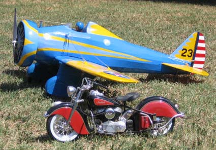
Attached are pictures of my first original design scale model, a P-26 Peashooter, that was my entry in E-Zone, Scale Electric Forum's Fun Scale Design and Build-Off contest. (Contest was my idea.)
The P-26 didn't maiden by the deadline but got most E-Zoner votes and an honorable mention/nice wood plaque in non-flying category. Model has 40" wingspan, weighs about 38 oz. ready to fly. Huge dummy Wasp and 6" speed ring require lots of watts and 11"-12" props. Final successful power setup is Scorpion 3008/32 outrunner and X-Caliber "Black Knight" 3S 2200 20-C from Innov8tive Designs (Lucien Miller). This pulls 25 amps WOT and gives over 100 watts per pound on an 11x7 GWS Direct Drive prop and scale-like flight speeds. The model is stable and flies like it's namesake. It tends to fall out of loops like my old Gee Bee "E" Sportser.
The wingspan, aileron area, and tail feathers were slightly enlarged, landing gear was shortened and spread wider apart and the nose lengthened slightly for easier ground handling, etc. Rudder and elevator linkage is pull-pull. The radio is a Spektrum DX-6 with Park BEC to feed the amp hungry receiver and four micro servos.
There will be a follow on contest starting in December 2007 for scale multi-engine prop planes and EDF jets.
Hope the weather is tolerable where you are. I was born in Stevens Point, WI.
Gary Gullikson
Garden Grove, CA
Editor Harbor Soaring Society Newsletter, "Plane Rap"
(I remarked how much I liked the photo with the Indian in it and Gary wrote back with the following. KM)
Here's a picture of me on my full size '48 Injun Chief. It's my second one. I have owned it since 1969, getting too arthritic to kick it over. I bought the first one in 1953 at age 15 1/2, was one of the few Indian riders in Milwaukee WI.
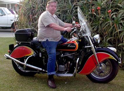
Don't I look "dashing" on it? (LOL!!!!!)
I have threatened to sell my Chief but my kids won't hear of it. They grew up with it.
My oldest daughter, mother of two, suburban housewife, won a new Vespa scooter and rides it quite a lot. My 46-year-old son rides a Yamaha super bike. I can't remember the "R"-number.
Gotta go charge "batteries" for tomorrow's flying session at club field, Fairview Park, Costa Mesa. We have sailplanes and a whole variety of electric sport and scale models and choppers of all sizes flying 7 days a week until the strong sea breezes come up around 11:00 A.M.
I currently am flying a 48" Cessna 140 from Pat Tritle's short kit, a 42" Berkeley Stinson Reliant SR-7, a Comet 54" Aeronca Chief, and my 40" P-26 Peashooter. All are electrics. I have many old kits from Ebay, etc., to convert and a couple of glow planes that I need to get back in flying condition.
Return to "What's In This Issue"
Microx Taylorcraft
From Bud Carlson flicka5@madbbs.com
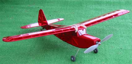
You published images of my "bitty bipe" a few years back. Here is my latest conversion, which is an old Microx glow kit left over from the 1970's. It is the Microx Taylorcraft kit designed for Cox .049 power. The W.S. is 38" and the weight "wet" is 19 oz. giving a wing loading of 13oz./sq. ft.
I am using a Hobby Lobby XT400 brushless outrunner with a 3-cell, 1500mAh Kokam lithium battery and a 9x4 slo fly prop.
It cruises nicely at about 50% power. I used the wood sizes that came with the kit and didn't attempt to lighten the structure for electric. Landings on a rough grass strip have already validated my decision to build for glow operation as the kit was designed. Still need to install the wing struts and wheel pants/landing gear covers as supplied in the kit.
I blindly followed the CG recommendations as shown on the Microx plan sheet, which put the CG around the rear wing spar. This point for balance gave a slight nose down to level position of the model ready to fly with no dead weight balance required. I hand launched the first flight while a good friend of mine operated the transmitter and with 35 years of RC flight control experience on his part, he had all he could do to get it back in one piece as it acted very tail heavy. I went back and looked at the plan and the flat bottom wing design. The rear spar is about 1/3 wing chord while all the flat bottom "Clark Y" type airfoils (no wing taper) usually call for a 1/4-chord point to balance.
So, I added lead weight to the nose until I got a slight nose down position of the fuse balancing at 1/4 chord. The next flight was a big improvement with less than 1.5 oz. of lead added to the motor compartment.
I can't believe that in all the years Microx sold this Taylorcraft kit for 1/2A, that thisCG problem wasn't fixed years ago on their plan. I know my Microx kit purchased at an RC auction was old and perhaps later plan versions show a 1/4 chord CG position?
I now have some twenty flights so far and it is flying very nicely and smoothly.
I believe that I got a 73 watt reading at full power.
I am very pleased with the $20.00 motor performance and how electric power has progressed to great thrust levels per motor plus battery weight in a few short years.
Return to "What's In This Issue"
Upcoming EFO Meeting Info
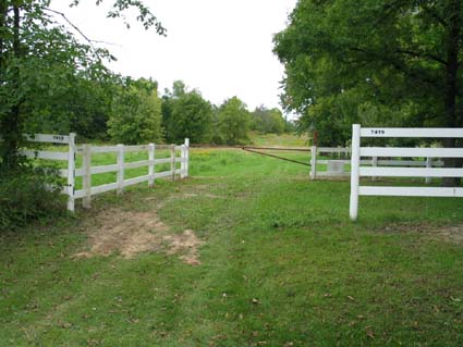
The photo above shows the NEW entrance to the Midwest 7 Mile Rd. Field. It is the gate past the second white fence on the north side of the 7 Mi. Rd. It is past another house from the one shown last month and about 1.4 miles from Currie Rd. It is directly across from Peter Waters' house. The address is posted on the fence and is 7419 Seven Mile Road. There is a second gate that you pass through about 1/2 way into the field. Just follow the most used "path." IMPORTANT! Channels 36 & 56 may NOT be used at this field!
Return to "What's In This Issue"
| Table 1 - Battery Weight |
| # M1 | Weight | Weight |
| Cells | oz. | grams |
| 2 | 5.70 | 162 |
| 3 | 8.55 | 242 |
| 4 | 11.40 | 323 |
| 5 | 14.25 | 404 |
| 6 | 17.10 | 485 |
| 7 | 19.95 | 566 |
| 8 | 22.80 | 646 |
| 9 | 25.65 | 727 |
| 10 | 28.50 | 808 |
| Return to article |
| Table 2 Imperial |
| # M1 | MCA | Min. Wing | Max. Wing |
| Cells | Wt. (oz.) | area sq.in. | area sq.in. |
| 2 | 16.2 | 285 | 350 |
| 3 | 24.3 | 375 | 460 |
| 4 | 32.4 | 450 | 550 |
| 5 | 40.5 | 525 | 640 |
| 6 | 48.6 | 590 | 725 |
| 7 | 56.7 | 650 | 800 |
| 8 | 65.7 | 715 | 880 |
| 9 | 72.8 | 775 | 950 |
| 10 | 81.0 | 830 | 1020 |
| |
| Table 2a Metric |
| # M1 | MCA | Min. Wing | Max. Wing |
| Cells | Wt. (g) | area dm^2 | area dm^2 |
| 2 | 459 | 18.39 | 22.58 |
| 3 | 689 | 24.19 | 29.68 |
| 4 | 919 | 29.03 | 35.48 |
| 5 | 1148 | 33.87 | 41.29 |
| 6 | 1378 | 38.06 | 46.77 |
| 7 | 1607 | 41.94 | 51.61 |
| 8 | 1863 | 46.13 | 56.77 |
| 9 | 2064 | 50.00 | 61.29 |
| 10 | 2296 | 53.55 | 65.81 |
| Return to article |
| Table 3 |
| # M1 | Motor | Motor | Motor | Motor |
| Cells | Weight g | Weight g | Weight oz. | Weight oz. |
| 2 | 67 | 133 | 2.3 | 4.7 |
| 3 | 100 | 200 | 3.5 | 7.1 |
| 4 | 133 | 267 | 4.7 | 9.4 |
| 5 | 167 | 333 | 5.9 | 11.8 |
| 6 | 200 | 400 | 7.0 | 14.1 |
| 7 | 233 | 467 | 8.2 | 16.5 |
| 8 | 267 | 533 | 9.4 | 18.8 |
| 9 | 300 | 600 | 10.5 | 21.2 |
| 10 | 333 | 667 | 11.7 | 23.5 |
| Return to article |
| Table 4 |
| # M1 | | | Diameter | Diameter |
| Cells | Kv | Kv | inches | inches |
| 2 | 2660 | 2100 | 7 | 9 |
| 3 | 1550 | 1200 | 9 | 11 |
| 4 | 1060 | 840 | 10 | 12 |
| 5 | 790 | 600 | 11 | 14 |
| 6 | 620 | 490 | 12 | 15 |
| 7 | 500 | 400 | 13 | 16 |
| 8 | 420 | 330 | 14 | 18 |
| 9 | 360 | 285 | 15 | 19 |
| 1 | 315 | 250 | 16 | 20 |
| Return to article |
| 5S Possible Motors |
| Weight 167g-333g | Kv 600-790 | Prop Dia. 11"-14" |
| Brand/# | Weight g | Kv | Price | Source | Notes:
(*NUPDA - No Usable Prop Data Available)
DC - Trusted Drive Calculator
Derived Data |
| TowerPro 3520-7 | 262 | 615 | $25.00 | Source | DC 1-deg timing
12x10E-70mph-38 amps
13x8 sport-57mph-35 amps
14x7E-49mph-37 amps |
| TowerPro 3520-6 | 262 | 730 | $25.00 | Source | DC 0-deg timing on Jeti Spin 44
12x6E-53mph-35 amps
11x8E-60mph-37 amps
Measured Kv 727 |
| HXT 42-50-A | 195 | 600 | $29.95 | Source | DC 13x7 sport-52mph-35 amps
13x6.5-49mph-35 amps
12x8E-60mph-34 amps |
| HXT 42-50-A | 195 | 700 | $33.66 | Source | NUPDA, don't be confused.
Two motors, same number
different Kv |
| HXT 42-63 | 298 | 600 | $48.14 | Source | Idle amps seem high @ 6.3A, tried to use data in DC, wildly inaccurate |
| BP A4120-7 | 298 | 610 | $55.95 | Source | NUPDA |
| Rimfire 42-50-600 | 198 | 600 | $59.99 | Source | Says 4S Li-Po 14x10E, 6300RPM ~37 amps |
| Welgard C4250-07 | 203 | 695 | $65.95 | Source | NUPDA |
| Rimfire 35-48-700 | 170 | 700 | $67.99 | Source | Says 4S Li-Po 13x6.5E, 7980RPM ~38 amps |
| Rimfire 42-60-600 | 268 | 600 | $74.99 | Source | NUPDA |
| Skyshark Lightning 50 | 300 | 600 | $79.95 | Source | Based on data posted for 4S Li-Po looks like a 13x6 would be about 35 amps or so |
| Scorpion 3032-12 | 224 | 687 | $79.99 | Source | NUPDA |
| Hyperion Z3025-12 | 186 | 665 | $82.95 | Source | Limited prop data says 13x6.5E, 7980RPM @ 38 amps |
| Rimfire 50-55-650 | 298 | 650 | $87.99 | Source | NUPDA |
| Welgard C5055-06 | 301 | 628 | $89.95 | Source | DC 13x6.5E-48mph-38 amps
13x6 sport-45mph-35 amps
12x7 sport-54mph-34 amps |
| DualSky 4260CA-5T | 283 | 680 | $99.99 | Source | NUPDA |
| Hyperion Z4020-12 | 284 | 660 | $105.95 | Source | NUPDA |
| Hyperion Z4020-10 | 284 | 748 | $105.95 | Source | NUPDA |
| Hacker A40-12S | 264 | 610 | $109.99 | Source | NUPDA |
| Hacker A40-10S | 264 | 750 | $109.99 | Source | NUPDA |
| E-flite Power 46 | 290 | 670 | $109.99 | Source | DC 11x8E-67mph-~35 amps
11x8 sport-66mph-~36 amps
11x8.5E-70mph-~36 amps
12x7 sport-57mph-~37 amps
12x8E-65mph-~38 amps |
| Atlas 4020/12 | 326 | 650 | $116.90 | Source | NUPDA |
| AXI 4120/14 | 320 | 660 | $129.90 | Source | DC 12x7 sport-58mph-35 amps
11x8.5E-71mph-34 amps |
| Return to article |
| 6S Possible Motors |
| Weight 200g-400g | Kv 490-620 | Prop Dia. 12"-15" |
| Brand/# | Weight g | Kv | Price | Source | Notes:
(*NUPDA - No Usable Prop Data Available)
DC - Trusted Drive Calculator
Derived Data |
| TowerPro 3520-7 | 262 | 615 | $25.00 | Source | DC 1-deg timing
12x7 sport-61mph-~35 amps
12x8E-70mph-~35 amps
13x6 sport-52mph-36 amps
Measured Kv 615 |
| HXT 42-60/06 | 280 | 500 | $29.78 | Source | DC 12x10E-72mph-~37 amps
13x8 sport-59mph-~34 amps
13x9 Pat.-66mph-~35 amps
14x7E-50mph-~36 amps
14x8.5E-60mph-~38 amps
Measured Kv 560 |
| *HXT 50-55B | 300 | 500 | $42.33 | Source | It appears the Kv is ~500 so belongs here but the name says 600 not 500 I've posted.
DC 14x8 sport-55mph-36 amps
13x10E 69mph-36 amps |
| HXT 42-63 | 298 | 600 | $48.14 | Source | Idle amps seem high @ 6.3A
tried to use data in DC, wildly inaccurate |
| BP A4120-7 | 298 | 610 | $55.95 | Source | NUPDA |
| Skyshark Lightning 50 | 300 | 600 | $79.95 | Source | NUPDA |
| Rimfire 42-60-480 | 268 | 480 | $74.99 | Source | ElectriFly Web site says 13x10E @ 42 amps on 5S Li-Po |
| Rimfire 42-60-600 | 268 | 600 | $74.99 | Source | NUPDA |
| Rimfire 50-55-500 | 298 | 500 | $87.99 | Source | NUPDA |
| Welgard C5055-08 | 307 | 480 | $89.95 | Source | NUPDA |
| DualSky 4260CA-6T | 283 | 566 | $92.95 | Source | NUPDA |
| Hyperion Z4020-14 | 284 | 574 | $105.95 | Source | DC 14x8 sport-52mph-37 amps
13x10E-66mph-37 amps
12x10E-67mph-34 amps |
| Hyperion Z4020-16 | 284 | 504 | $105.95 | Source | NUPDA |
| Hacker A40-14S | 264 | 530 | $109.00 | Source | NUPDA |
| Hacker A40-12S | 264 | 610 | $109.99 | Source | NUPDA |
| Himax HC5018-530 | 280 | 530 | $115.99 | Source | NUPDA |
| Atlas 4020/14 | 326 | 500 | $116.90 | Source | Web site says a 14x9 on 5S Li-Po |
| Hacker A40-10L | 349 | 500 | $119.00 | Source | NUPDA |
| Hyperion Z4025-12 | 356 | 486 | $119.95 | Source | NUPDA |
| Hyperion Z4025-10 | 356 | 560 | $119.95 | Source | NUPDA |
| AXI 4120/18 | 320 | 515 | $129.90 | Source | DC 12x10E-73mph-34 amps
13x10E-71mph-37 amps
14x8.5E-57mph-36 amps |
| Return to article |
Return to "What's In This Issue"
|

