 |
Flying High With Electric Power!
The Ampeer ON-LINE!
Fly the Future - Fly Electric! |
Site Table of Contents
| President: | Vice-President: | Secretary/Treasurer: |
| Ken Myers | Richard Utkan | Rick Sawicki |
| 5256 Wildcat | 240 Cabinet | 5089 Ledgewood Ct. W. |
| Croswell, MI 48422 | Milford, MI 48381 | Commerce Twp., MI 48382 |
| (810) 679-3238 | (248) 685-1705 | 248.685.7056 |
 | ||
| Board of Directors: | Board of Directors: | Ampeer Editor |
| David Stacer | Jack Lemon | Ken Myers |
| 16575 Brookland Blvd. | 8908 Sandy Ridge Dr. | 5256 Wildcat Rd. |
| Northville, MI 48167 | White Lake, MI 48386 | Croswell, MI 48422 |
| 248.924.2324 | 248.698.4683 | 810.679.3238 |
| Mailed Ampeer subscriptions are $10 a year US & Canada and $17 a year world wide. FREE on-line! | ||
| The Next Meeting: Date: Saturday, Sept. XX Time: 10:00 a.m. Place Midwest RC Society 5 Mile Rd. field, Northville Twp., MI - Just west of Plymouth, MI | ||
|
I need to contact one of the vendors that was at the Mid-Am this summer. He is from Ohio, I believe the Columbus area. He had a sign set up in front of his area that read "Quiet Flyer R/C". If he could contact me, I would appreciate it. If anyone knows how I can contact him, please let me know.
By Ken Myers In the August 2006 Ampeer I noted two sources for the larger capacity, relatively inexpensive, yet quite useful, lithium polymer (Li-Po sometimes Li-Poly) batteries for these types of RC planes: skysharkrc.com and truerc.com. I am going to make some very specific recommendations for using these batteries. If you are not already flying electrically powered RC planes, you MUST have these items before using the following recommended power systems with Lithium Polymer batteries. Li-Po Battery Charger: It must be capable of charging a four-cell through six-cell battery in series or individually through the tap connector. I use and recommend the Astro Flight 109, a series charger. Li-Po Battery Balancer: It must be capable of balancing a 4-cell through 6-cell pack. The Astro Flight Blinky works well with these packs. Whattmeter: Like Kleenex for facial tissue, "whattmeter" has come to mean a device for measuring fairly large current draws above and beyond what a typical digital multimeter can do. Again, I use and recommend the original Astro Flight Whattmeter, although I also very highly recommend the Hyperion Emeter, which I also use all of the time. The Emeter also includes a built-in tachometer and a host of other nice features including data capture to the unit itself and programming capability for the Hyperion ESCs. No computer necessary. Digital Multimeter: The digital multimeter is used to read the individual cell voltages through the cell tap connector on the battery pack. The meter should be good enough to be fairly accurate. I use some from Radio Shack. They are okay, but not super great, nor super expensive. Usually, the really cheap ones, like from Harbor Freight, are not quite accurate enough. The one I use the most is the Model #22-168A from Radio Shack. These devices are all essential tools to have BEFORE running up your power system for the first time! Ken's Tip #1: Have the right tools or Do Not Use Li-Po batteries! Keep a battery log or journal so that you can have a record of how your batteries are holding up over time. The log can be paper or electronic. I use a spreadsheet. Before adding your battery connector(s) of choice, (I use Anderson Power Poles (APP)/aka Sermos connectors) use the volts function of the digital multimeter to check all of the individual cell voltages through the cell tap connector. I use leads from my digital multimeter that have small alligator clips holding straight pins. I do not use the typical probes that come with the standard leads. I'm afraid that if I used the standard probes I might short the lead probes together. I measure from the most negative cell through the least negative cell. It doesn't really matter what order you do it in, just always do it the same way for your log. I insert the negative lead straight pin into the hole in the connector and touch the positive lead straight pin to the bare metal of the next pin in the connector and log the voltage reading, then I move the negative pin to the next hole in the connector and the positive pin to the bare metal on the connector next to it, continuing to log the volts between each move until all the individual cell voltages have been recorded. 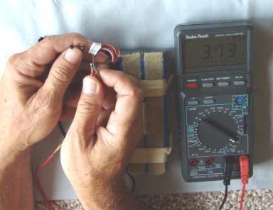 WARNING #1: Do not short the lead probes, clips or pins! Do not be complacent! Do this procedure very, very carefully. Always pay attention to what you are doing. If you short a cell, even for a fraction of a second, you will have most likely ruined the cell and maybe the pack. It is also possible that there could be a fire. Do this measuring in an area where there is no combustible material present. If the pack voltages on arrival are within about 0.01 of a volt and 0.02 of a volt of each other, the pack should be fine. Packs should arrive with all of the cells being 3.70v each or higher, although 3.60v is not unheard-of. Three of my four packs arrived this way with the voltage readings in the mid-3.7v to 3.80v range. If the pack cell voltages measure close to each other, as noted above, the battery to ESC connector(s) can now be very carefully added to the pack leads. Do only one lead at a time, keeping the other lead safely wrapped and away from the lead you are working on. Once the battery connector(s) have been added to the pack, it can be charged and balanced. If the pack is out of the above range, contact the supplier and ask him what to do. One of my Skyshark RC 4S 4000mAh packs arrived with the following voltages; 3.73, 3.80, 3.77 and 3.80. After a discussion with Mike at Skyshark about this, I did the following. I carefully added my APP connectors to the battery leads for the battery to ESC connection. I put the pack in my fire safe ammo can. I placed the can away from all combustible materials and did a partial charge using the AF 109 charger. This partial charge brought the voltages up to 3.91, 4.01, 3.95 and 4.00. The voltages were then in the range for the AF Blinky to balance the individual cells. After the Blinky stopped blinking, and the pack was balanced, I measured the individual cell voltages through the tap connector once again, and found all the individual cell voltages to be very close to each other. I then did a full charge on the pack and used the AF Blinky balancer to bring all the cells into balance after removing the pack from the charger. After 18 flights and recharge cycles this pack stays in balance very well with no problems experienced at all. The cell that originally measured 3.73v is right in sync with the rest of the cells. My log shows that the individual cells have never been more than 0.01v apart after any flight or when I measure them again before charging, which may be several days later. According to my notes, the AF Blinky says that this pack is just fine after charging the majority of the time, and no balancing is necessary. Ken's Tip #2: Always use the AF Blinky to balance every pack after every charge. I try to do it about an hour after the charge to let the cells settle down a bit. Once you have your complete power system, motor, battery, props and electronic speed control (ESC), it is time to static test it. Static testing can be done on the bench or with the power system mounted in the actual airframe. Wherever the power system is mounted, be extremely sure that it is mounted very securely and that the prop adapter is secure on the motor shaft. As you will see in the recommendations that follow, I am recommending that the prop load the motor to about 31 to 37 amps statically. Securely mount the prop, which I call the "Initial prop", to the prop adapter. Plug the charged Li-Po battery into the "source" lead of the Whattmeter. The ESC output leads should have been already attached/connected to the motor leads. Turn on the transmitter and then the onboard radio battery. Be sure the throttle stick is in the off position. Attach the "load" lead of the Whattmeter to the ESC input lead. Slowly run up the prop a bit to determine that the prop rotation is correct. If the prop is turning backwards (pushing air away from the motor), swap any two leads on the connection between the ESC and motor. Once the prop is turning in the correct manner, slowly advance to full throttle and note the amp draw on the "Whattmeter" at full throttle. The amp reading should be somewhere between 31 and 37 amps for my recommendations. Don't bother looking at the amp draw at anything but wide open throttle (WOT), as it doesn't indicate any useful information when the throttle is not fully opened. Allow the motor to run at full throttle for 10 to 15 seconds to "warm up" the battery. Shut the throttle down, wait just a few seconds and then advance to full throttle noting the maximum amp draw. It should be between 31 and 37 amps. If the amp draw is in this range, try flying with that prop. WARNING #2: Never run a full pack through the motor statically! All of the measurements needed may be obtained in a matter of seconds without rushing. If the amp draw exceeds 40 amps during the initial static test with the recommended prop, immediately shut the throttle down. Using the following system recommendations, exceeding 40 amps for a few seconds is not going to cause a problem for the battery, ESC or motor, so don't panic, I've left "headroom" for the safety of the expensive equipment. Replace the prop with the "Lower value" prop I have recommended and repeat the test. If the full throttle amps, after the pack warming, are lower than 30 amps, replace the prop with the "higher value" prop that I have recommended and repeat the test. At high elevations it might be necessary to use the "Higher value" prop and at low elevations to use the "Lower value" prop to keep the amp draw in the recommended range for these systems. Temperature, humidity and barometric pressure also play a role in determining how "hard" the prop is pulling and thus the amp draw reading on any specific day. Once the system is set up in the plane, it is time to go fly. Head out to the field and have a ball. If you have only used the charged battery to do the static testing, Do Not Recharge the pack! Go ahead and fly a five-minute flight or so to get acquainted with your new plane and its power system. Then you can recharge and continue to fly. Ken's Tip #3: Do not re-peak Li-Po batteries! Peak is really not the correct term, but don't charge them again until they have been discharged. My favorite means of discharging is flying them. But wait! What plane and what power system? That is what this whole article is about! One of the biggest problems in choosing a power system, for a given project, is that there are so many choices that will work. I am purposely limiting the choices to simplify and guarantee success. To answer the inevitable questions, "Can't I...?" and "Won't this...?" Yes you can, and it probably will. That's really not meant to be a smart-alecky statement. If you know enough to ask the questions, then you probably can answer them as well. The mission is a factor that many people overlook when recommending power systems for RC planes. The mission for these mid-size sport and sport scale recommendations is to use the relatively inexpensive Li-Po batteries, which I have recommended, and provide a plane that has good to very good performance. It should be noted here that adjectives are very subjective. When I say good to very good, I mean that the plane flies on its wing, has reasonable but not out of sight vertical performance and does very decent size loops in relationship to its physical size. All other maneuvers, that the design of the plane and the pilot are capable of, will also be done well. If that is what you are looking for, you have found the information you need to do it. If you want to fly 3D, pylon race, fly in a park, fly tiny indoor planes, monster planes or soar, these recommendations are not for you. Similar batteries may be obtained from Skyshark RC (www.skysharkrc.com) or True RC (www.truerc.com). Both batteries are very similar. You can check their sites for current pricing and availability. The motor and ESC can be obtained from Hobby Lobby (HL) (www.hobby-lobby.com). Most of the time HL has combos for the motor and ESC, and sometimes the mount is included for free. Watch for specials. Motor: AXI 2826/12 (6.4 oz./181g)
The onboard radio system (8 oz./227g), that I am recommending, is the same for all three of the plane/power system recommendations and can be found near the end of this article. Wing area: 478 sq.in./30.8dm^2 - 590 sq.in./38dm^2
Similar batteries may be obtained from Skyshark RC (www.skysharkrc.com) or True RC (www.truerc.com). Both batteries are very similar. You can check their sites for current pricing and availability. The motor and ESC may be obtained from All e RC (www.allerc.com). They have combos. Watch for specials. Motor: Hyperion Z4020-14 (9.5 oz./270g)
The onboard radio system (see previous note) Wing area: 550 sq.in./35.48dm^2 - 675 sq.in./43.5dm^2
The battery can be obtained from Skyshark RC. You can check their Web site for current pricing. The motor and ESC can be obtained from Hobby Lobby (HL). They have combos. Watch for specials. Motor: AXI 4120/18 (11.3 oz./320g)
The onboard radio system (see previous note) Wing area: 625 sq.in./40.3dm^2 - 770 sq.in./49.7dm^2

Sonic 500 image from Hobby People site ARF example/4S1P: The Sports Aviation Sonic 500 found at Hobby People (www.hobbypeople.net) has a Wing Area of 504 sq.in. It fits into the 4S1P power/plane recommendation. 
Sig Kougar image from Sig Mfg. site Kit built example/5S1P: The Sig Kougar has a Wing Area of 540 sq.in. The wing area puts at the "large" end of the 4S1P system, but... The highest advertised weight of the Kougar is 6 lb. or 96 ounces. From my records I know that, in general, the CAW for a typical glow plane is about 60% of the highest advertised weight. The advertised RTF weight for this plane is 96 oz., which suggests a CAW of ~58 oz., which is too heavy for the 4S1P system. With the CAW fitting in the 5S1P category and the wing area just a tad smaller than the recommended 550 sq.in., it would be best to use the 5S1P system in this plane. 
Lotsa Amps image from Model Aviation site Scratch built example/6S1P: the Lotsa Amps construction article featured in the June 2006 Model Aviation designed by Dick Sarpolus, has a Wing Area of 675 sq.in., which is the maximum wing area for the recommended 5S1P system. The 5S1P system could be used, but for even better performance, the 6S1P system can be used because it places the wing area more toward the middle of the recommended range. The author/designer chose to recommend a power system that is very similar to my recommended 4S1P system. His version of this plane has a Cubic Wing Loading (CWL) that places it in the Park Flyer class. That is just fine for how he wanted it to fly, but if a smooth flying, wind handling plane is desired, it would be best to increase the RTF weight of the plane and use the 6S1P system.
These planes should not use a "cheap" Chinese receiver. I use, and recommend, the FMA M5v2 (www.fmadirect.com) or equivalent weight "good" receiver! My preferred servos, for these size and weight planes, are the Hitec HS-85BB or MG and if retracts are used, an appropriate servo for mechanical or pneumatic retractable landing gear. The electronic speed controls have already been noted. I recommended the ESC available from where you get your motor as a convenience and chance to save some money using a "combo" deal. I recommend a 500mAh - 700mAh receiver pack over a UBEC electronic battery eliminator circuit. About one and a half ounces is a very small price to pay in weight penalty on this size plane. A well maintained receiver battery should have less potential for failure than an electronic device, although it could be argued in just the opposite direction. The choice is yours. Safety WARNING: These types of planes are ONLY for the experienced RC flier. Li-Po batteries are EXTREMELY fragile and can easily be damaged in a crash or even a hard landing. They require extreme care in charging and storage. The potential for fire is very real. If you are not a flier who spends more time flying than repairing, or you are not willing to invest in the necessary tools and provide the safest possible environment for the charging and storage of these batteries, these recommendations are not for you! Li-Po batteries are not for you! Ampeater II:
Details: Length overall: 33.5 in (including prop & spinner)
Wingspan: 48 in. Area: 318.5 sq in Chord: 7 in. Airfoil: Clark Y (12%) Dihedral: 1 in. (each tip) Incidence (root): 3 deg. Tip washout: approx. 1.5 deg. 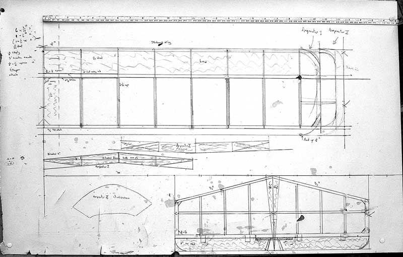
Click image for larger view. Horizontal Tailplane Span: 16 in Mean chord: 5 in. (including elevator): Area: 80 sq. in. Elevator: 1 in. Area: 14 sq. in. Height: 6 in. Mean chord: 4.75 in. (incl. rudder): Area: 28.5 sq. in. Rudder: Mean chord 1.5 in. Area: 9 sq. in. 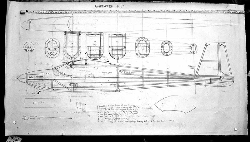
Click image for larger view. Fuselage Length to front motor mount: 32 in.
Graupner Speed 400, 6V w/(Graupner, in-line) Gearbox 4:1 Prop: Graupner 11x 8 Current draw (static) is 6.3 amps at 3800 rpm, volts down to 6.9 Battery: 8 cell 1050 KAN NiMH pack (Overlander) Down thrust: 3deg. Jeti JES 10 with BEC Rx: GWS Naro R6N Tx: Futaba Challenger, 35 MHz Hitec HS81 (rudder), SuperTec Naro (elevator). (*Would have been Hitec HS81 but it died) Hitec HS 80 (ailerons)
Fuselage: 3/16 in. square medium balsa, with formers and battery box of 3/32 in. lite-ply Stringers 3/32 sq balsa Tail feathers: 3/16 in. square medium balsa, Elevator 1 in. by 1/4 in. medium hard balsa trailing edge stock. LE: 3/8 in. sq. medium balsa False TE: 1/4 in soft balsa TE: 3/4 in. by 1/4 in. hard balsa trailing edge stock Ailerons: 3/4 in. by 1.4 in trailing edge stock from 9 in from C/L to 18 in from C/L Spars: 1/4 in. hard balsa. 2.25 in. aft of LE top and bottom Upper surface sheeted with 1/32 in. soft balsa sheet LE to spar. Centre section sheeted with 1/16 in. soft balsa for full chord 1.5 in. either side of centre line. Ribs: 1/16 in. soft balsa: first 2 ribs 11/2 in. apart then at 3 in. spacing. Ribs capped with 1/4 in. by 1/32 in. balsa aft of spar. Dihedral braces: 1.5 mm birch ply fore and aft of spar. Full depth for 3 in. tapering to zero on bottom spar at 6 in. each side of centre line Covering: Transparent Solarfilm Control throws: (pre-flight starting values)
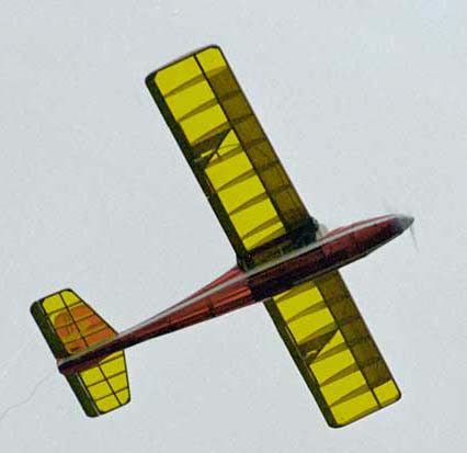
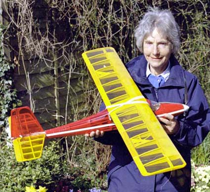
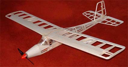
The Story Behind the Plane! Dear Ken, It's taken a while but it's a long story. Ampeater II was completed early in the New Year (2006), but the first flights were a disaster, and it was a while before the problems were fixed. Then further flights were delayed by a run of lousy weather, Eventually I had a proving flight that went well, but no one had a camera handy. Then we went away in April for a protracted trip to the antipodes from which I have only recently returned. Since then I've managed to get some in-flight photos, so here is the story and pictures. There is a picture of the skeletal stage showing the old style balsa-basher's formers and stringers. No one wants to bother with that these days, but its prettier than the slab-sided Ampeater I. (Info in the February and September 2004 issues of the Ampeer. KM) I lowered the cabin height to give a more elegant profile, reduced the wing incidence as I'd had to use a lot of trailing edge packing on Ampeater I, and I reduced the dihedral for a bit more maneuverability. The first version was so stable it would make a good free flight. Since the previous formula worked well I didn't change the tail feathers, moment arm or overall length, but added three inches to the span to keep the wing loading to the previous value because I'd added ailerons and the associated servo. In fact the overall weight came out little different. On its first outing it climbed away from a hand launch, needed some trim to cure a left turn tendency, then I did a gentle right turn with the ailerons, but when I tried a left hand circuit it suddenly went into a spiral dive and I only got somewhere near wings level with the ailerons before it cart wheeled into the nearest ploughed field. There was not much damage, but the stabiliser (tailplane to us) needed gluing on again, and the lovely covering was no longer so elegant at the back end. The reason? I'd relied on so-called servo tape to affix the servos, and the rudder and elevator servos came adrift. That was big mistake Number One. They are now fixed down in balsa boxes. They had to be surface mounted on the servo platform because with the lower cabin the servos couldn't drop through into the battery box area. I found the aileron servo (in the wing centre section) also needed reinforcement. Having fixed all that I went out with renewed confidence, only to find that once again on initiating a left turn I got a nasty spiral dive into the mud, fortunately it was winter and muddy. The fuselage structure was OK, but the battery went through the two forward formers including the motor mount 'firewall'. That needed a bit more of a rebuild with the forward hatches removed, but the main structure was still intact. Then I found there was a nasty wing warp causing the problem, and with a dose of steaming and application of the iron I finally got it straight. I decided then to tape off the ailerons and revert to rudder-elevator control until I could make sure I could cope. This time we had a camera (small compact film camera with 38-150mm zoom). To my great relief it flew away straight and needed little trim. It is a bit twitchier than its predecessor, goes considerably faster and looks to have a better glide. Less drag and a bit more wingspan presumably helps. It still flies slowly without much of a stall, and on the glide will descend vertically in 'mushmode' with full up elevator if there is even as light headwind. I didn't get flying again until just before we went away. Last week it was hot and sunny and there were thermals about, so I had a flight lasting over 30 min, so it picks up lift OK. I only had one flight because I found the window glazing was coming adrift, so quit when I was ahead and went home happy. I think I'll have a few more rudder-elevator flights before re-coupling the ailerons. First impressions were that they were too small to be very effective, but I'm unused to using them for the primary turning control and tend to forget the rudder. I'll take things in small steps, but it looks promising. Its not going to be aerobatic, but I'm hoping the ailerons will do something. So that's why its been a long time sending you the story. I still enjoy the Ampeer; there were several waiting when we got home. Thanks for keeping me in the loop. I can see the technology is moving on by leaps and bounds, so one day maybe I'll lash out on a brushless set-up and maybe even Li-Po's. But there's still a lot of fun and mileage in my old brushed Speed 400s and Futaba Challenger Tx. With best wishes,
Amp Hour Detect Circuit
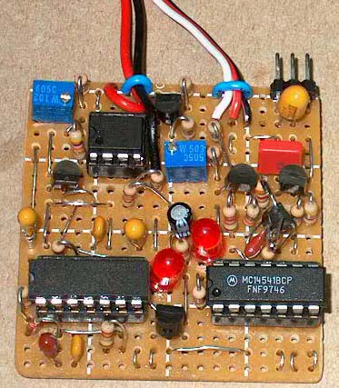
Hi Ken, Thought you'd be interested in this. The picture is of an experimental proof-of-concept Amp Hour Detect Circuit. It monitors on-board current drain via a 5-milliohm shunt and when a preset level of amp-hours is drained from the pack, the circuit "wobbles" motor power to let the pilot know. Basically, it's a sort of timer, but the elapsed time per-se does not matter. Rather, it's "used" Ampere-hours that count. In use, the AHD plugs in-line with the Rx and ESC cable (like an LCDC), and to the shunt in the (+) battery lead. No battery taps connector (balancing connector) is involved. I've been playing with this idea since reading repeated comments on-line about "...only draining a pack 80% of its capacity..." The accompanying recommendation is usually to watch the flight time. But flight time can be a big variable depending on the flight profile and so time does not really measure battery drain. The AHD does. Ultimately, I can imagine a sort of LCDC/AHD combo circuit as sort of a "super protector" for Li-Po packs! Cordially,
Okay folks, what do you think? Anyone interested in more details? KM
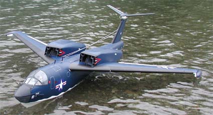
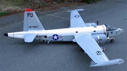
Ken Myers's Newest Plane Because of the early demise of my Low-Stik, I needed a new plane quickly. I selected the Sportsman Aviation Ryan STA from Hobby People because I was very satisfied with the Low-Stik. It has been a building nightmare, and a lesson in how NOT to design a model airplane. You can read my trials and tribulations with this build at: www.rcgroups.com/forums/showthread.php?t=557165 Two Navy Planes: I have not flown either model, but have taxied both of them. In the case of the P6M-2, shortly after my taxi tests and subsequent modifications, my wife was diagnosed with colon cancer, so virtually all of last year was taken up with her surgery and follow-on treatment. Fortunately, her health is good now, so I hope to make a flight attempt this summer (if it ever cools off).
Status: First taxi tests completed on 24 June 2004; model behaves satisfactorily in moderate wind and "sea state"; leaks in aft portion of hull. Following initial taxi tests, the model was allowed to dry. The probable source of the leaks was the hydro-flap cavities; they were covered with thin plastic (except for the actuator cable openings). In addition, the hull was re-sprayed and a larger servo was installed for the hydro-flap actuation. A second taxi and initial flight attempt are planned for late September/early October. Scale: 1/16, Wing Span: 77.2 in. Fuselage Length: 90.2 in. Wing Area: 1068.5sq.in./7.42sq.ft; Wing Airfoil: NACA 63A210 (modified to 12% thickness) Controls: spoilers (no ailerons); flaps; rudder; hydro-flaps; elevator Motors: Mega Acn22/20/2; Batteries: 1300mAhr, 10 cells/motor Fans: WeMoTec HW609, each with Castle Creations Phoenix 60Acontroller Total Weight: as built - 300oz/18.75 lbs Wing Loading: 40.4 oz/sq.ft. Construction:
My P2V-7 model is a 1/12th-scale, all-electric model of the P2V-7/SP-2H aircraft. The model's wingspan is 108 inches, with 7.2 square feet of area; the all-up weight is 23.5 lbs. with the 'test-set' of NiCads installed. The reciprocating motors are Astro 25's; the EDF's are powered by 600-size 'buggy' motors driving WeMoTek HW609 fans. It needs a hard-surface runway for take-off and, hopefully, flight. I have taxied the model, and discovered that I had to replace the 'mechanical' retracts with Robart struts and retracts (due to absence of a serious diet program for the model). The model was started about 2 years ago in an effort to involve a very close friend who was a P2V-7 pilot, and, ultimately, commander of the P2V-7 reserve squadron (VP-69) that flew out of NAS Whidbey beginning in November 1970. In 1975/76, VP-69 converted to P-3 aircraft. My friend retired from the Naval reserve in about 1985. Unfortunately, my friend's health declined and he was not able to participate in building the model. I had one ride in a P2V-7 from NAS Whidbey to NAS Denver, via NAS Alameda (now closed) in July 1958 after graduation from USAF single-engine jet pilot training; my friend was the pilot. The model was based on an enlarged three-view from Squadron/Signal publication #68 ("P2V Neptune in Action"); photos of a P2V-7 at Tillamook Air Museum, Oregon; photos of a P2V-7 nose section being restored at Arlington Airport, Washington; and Wayne Mutza's book, "Lockheed P2V Neptune, An Illustrated History;" Mutza's book is expensive, but is available from Schiffer Military/Aviation History, 77 Lower Valley Road, Atglen, PA 19310; phone: 610-593-1777. I also purchased the NATOPS flight manual to get a better understanding of the antenna system and other details I had to prepare drawings of certain components, e.g., the reciprocating and jet-engine nacelles; the MAD 'tail cone,' wing tanks, etc. The wing airfoil is a modified Eppler 197 profile (16.5% thick at the root, tapering to 10% thick at the tip); the vertical fin/rudder is Eppler 476 (13% thick); the horizontal stabilizer/elevator is also Eppler 476, but is 15% thick. All the airfoils were plotted with MacFoil (I'm a Mac user). The model is built primarily of balsa sticks and sheet, with a little foam in some areas. It has a fully detailed cockpit, operating 'Fowler-type' flaps, and retractable landing gear. I covered the model with Polycover polyester film, though some areas are painted. All the large 'decals' (national insignia, etc.) are stick-on vinyl done by Bill Fulmer. There are 11 servos in the model; it uses an Airtronics radio system. |
To Reach Ken Myers, you can land mail to the address at the top of the page. My E-mail
address is:
KMyersEFO@mac.com
EFO WEBsite: http://members.aol.com/KMyersEFO/