Initial Safe Center of Gravity (ISCG) By Ken Myers November 2011 Updated: January 2018 Selecting the initial safe fore and aft balance point (longitudinal balance point), commonly referred to as the CG, is important for a successful first flight on any aircraft. Having an initial safe CG (ISCG) can make or break a plane, literally. Roy Day stated in his article "Get the CG Right", "A nose-heavy airplane may fly poorly, but a tail-heavy airplane may fly only once." Keith Shaw stated in his Tech-talk to the EMFSO, "Fine Tuning the CG", "As the airplane gets close to its perfect center of gravity, the drag of the airplane drops dramatically, which means it takes less power to fly." He also noted, regarding the CG, "It really depends on what you want to do and what means something. If flying overhead with transparent covering is desired, then you can do anything. (Within reason. KM) If super long flight times mean something, then that means efficiency." Keith's statements imply a range of acceptable CG points and that the desired CG may vary with the purpose or mission and even with the pilot's skill level. The purpose of the initial safe CG (ISCG) is to get the plane flying so that the perfect and/or optimal CG may be determined for the plane's mission and the pilot's flying style and skill. Often times, the CG point or a CG range noted on plans, or in an instruction manual, does not indicate the ISCG. If the initial safe CG is not noted, it is possible for the plane to be uncontrollable during the first flight. The results are usually a 'broken' plane and 'broken' expectations. Only monoplane conventional plan forms are discussed here.
CG Balancers:
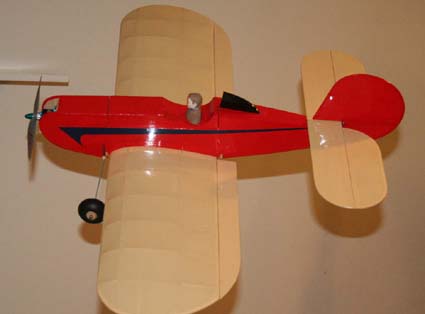
A common technique is to use the 'index finger' or 'index finger tip' method. The technique is especially useful at the flying field, but may be equally effective 'on the bench'. At the field, depending on the model's size, one or two people may perform the CG check. How the fingers are placed depends on the size of the plane. On small planes, a finger on each hand is used to suspend the plane. Larger planes may require two fingers on a hand and a helper using two fingers. The fingers are repositioned until what appears to be the datum line of the fuselage is horizontal to the ground. The technique is used with the aircraft either upright or inverted, depending on the wing's placement on the fuselage. The mass of the fuselage is 'below' the wing when the CG is being checked. The plane's CG is roughly shown by the finger position on the wing. It may or may not be the initial safe CG, but it is the approximate CG the plane has at the time of the test. A measuring device is not usually available at the flying field. The CG placement is "eyeballed" and its approximate relationship to the mean aerodynamic chord (MAC) is noted. After using the technique, and questioning the CG placement, experienced pilots may recommend adding some weight to the nose to move the CG further forward for the first flight. They are 'recommending' an initial safe CG. The ISCG may be set 'on the bench' using the 'index finger' method. The aircraft's initial safe CG is marked with a line segment on the wing's surface where the fingers will be placed. Only the initial safe CG line segments, closest to the tips, needs to be marked. 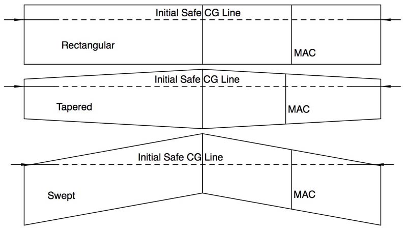 Three typical wing plan forms, shown in the illustration, demonstrate that there may be some instances where the line segment does not reach the tip. The line segments may be in front of the tip as shown on the Swept wing plan form. The marked wing is attached to the rest of the completed airframe. The fingers are placed on the initial safe CG line segments, usually near the tips. If the datum line of the fuselage is not horizontal when the plane is suspended at the ISCG, with the mass of the fuselage below the wing, some of the components inside the fuselage need to be repositioned in the airframe or weight added until the plane balances on the marked initial safe CG line segments. It is much better to do this before taking a new aircraft to the field. 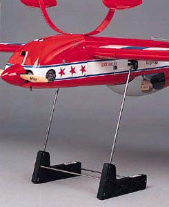
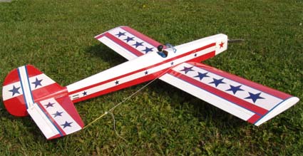
Great Planes C.G. Machine Click on photo for more information Commercial and homemade balancers are available. They are typically used 'on the bench'. The initial safe CG line segment is marked on the surface of the wing that is placed on the balancer. 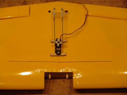 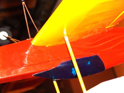 If the plane does not balance on the initial safe CG, either some of the components need to be repositioned in the airframe or weight has to be added until the plane balances on the marked ISCG line. 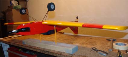 A Vanessa rig, a type of sling, may also be used, in a similar fashion to a balancer. 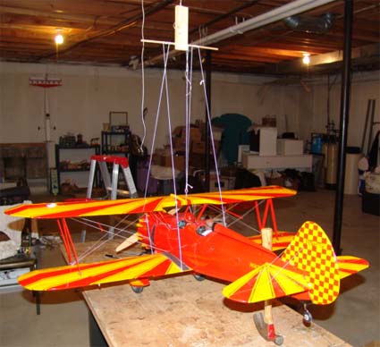 It can be used to set the initial safe CG. A biplane is shown in the photo. The method is the same for a monoplane. See also:
Many impressive mathematical formulas were developed to aid in the placement of the CG. Which formulas provide the initial safe CG? The Traditional or Conventional Wisdom CG: For a standard monoplane configuration, the traditional, or conventional wisdom, CG range is usually stated as between 25% and 33% of the wing's Mean Aerodynamic Chord (MAC). Some sources note up to 35% of the MAC. On a drawing, the wing's MAC is illustrated as a straight line from the wing's leading edge (LE) to its trailing edge (TE). The line divides the area of a wing panel (1/2 a wing plan form) in half. The 25% to 33% CG range tends to work well for planes with rectangular wing plan forms, long tail moments and/or large stabilizers. Some planes, many times scale types, don't have rectangular wings, long tail moments and large stabilizers. Scale planes and other unconventional conventionally designed planes present problems when locating the initial safe CG. The traditional formula provides a range, but is it the ISCG range or the perfect center of gravity range or something else? Does the simple traditional formula 'always' provide an initial safe CG? The MAC of a rectangular wing plan form is the wing chord distance located 1/2 way between the root and tip ribs. Locating the MAC of a tapered and/or swept wing is a bit more difficult. The more heavily tapered the wing, the more inboard the MAC location is. The aerodynamic center (AC) of a monoplane wing is located 25% rearward of the leading edge (LE) of the mean aerodynamic chord (MAC). 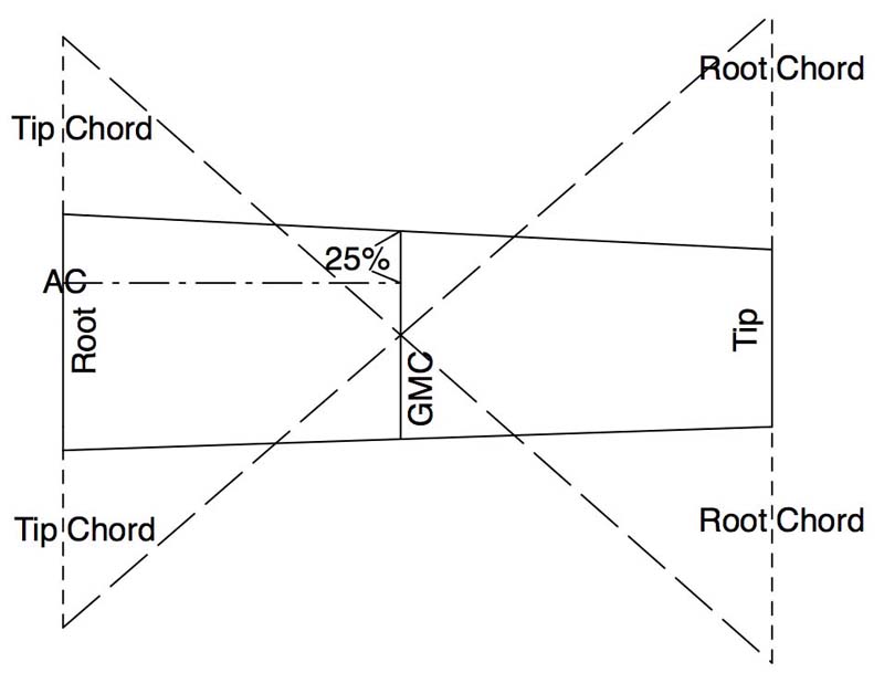 Without using mathematics, a simplified means of approximating the location of the MAC is to use a drawing. The resulting line, drawn parallel between the root ribs and tip ribs, is known as the Geometric Mean Chord (GMC) or the Standard Mean Chord (SMC). The CAD drawing shows only half of the plan form for a wing, a wing panel, with the root rib (inner most) shown on the left and tip rib (outermost) shown on the right. It makes no difference whether the wing panel area is tapered, swept or both. The process is the same. The wing's aerodynamic center (AC) is also shown on the drawing. The same procedure is used to identify the MAC and aerodynamic center (AC) of the horizontal tail (used later). The horizontal tail includes both the horizontal stabilizer and the elevator. 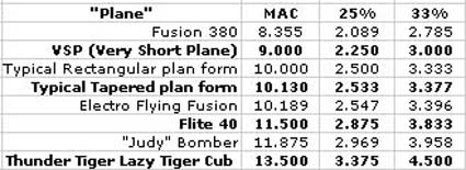
Table 1 Eight wing and horizontal tail plan forms were evaluated. The traditional CG range of 25% to 33% of the wing's mean aerodynamic chord (MAC) is shown in Table 1. Other mathematical formulas require some or all of the following information:
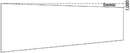
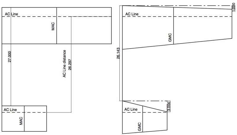
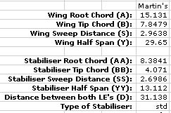
This wing panel has a 1" Sweep The Aircraft Center of Gravity Calculator is referenced as cg_calc. Aircraft Super Calculator 7.5.1 is referenced as cg_super_calc. Both of the referenced online calculators require the same user inputs. Two different plan form layouts were created using a CAD program. They had equal wing and horizontal tail areas. One was a rectangular plan form and the other had both the wing and horizontal tail areas tapered. The actual dimensions do not matter, as both plan forms remain proportional throughout scaling. 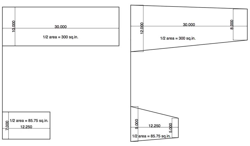 Actual dimensions, in inches, are shown on the drawings providing 'real' numbers for the online calculators and other formulas. Only 1/2 of each plan form is shown in the illustrations. The Geometric Mean Chord technique was used to create an approximate MAC for the wing and horizontal tail of the tapered plan form. The MAC for the rectangular plan form is at 50% the wing panel between the root chord and tip chord. The MAC line divides the surface area in half. 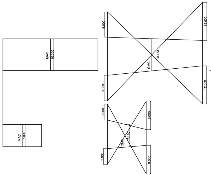 The Geometric Mean Chord construction lines were removed. The Aerodynamic Center (AC) lines were drawn with a dashed line at the 25% point on the MAC and the GMC, representing the MAC, on the tapered plan form. The plan forms were arranged so that the aerodynamic centers of each plan form were in alignment. 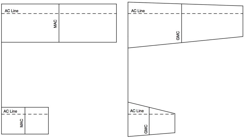 The distance from the leading edge (LE) of the root chord to the leading edge (LE) of the horizontal tail was noted on both plan forms. The sweep distances for the wing and horizontal tail of the tapered plan form were noted using dash dot lines. The distance between the aerodynamic center AC lines of the wing and horizontal tail was noted.
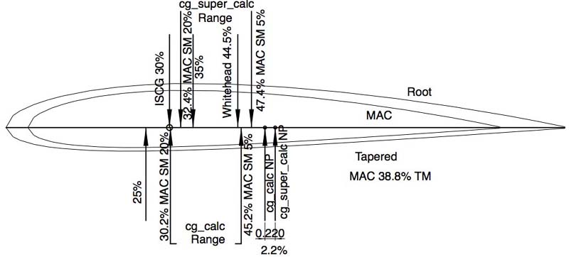
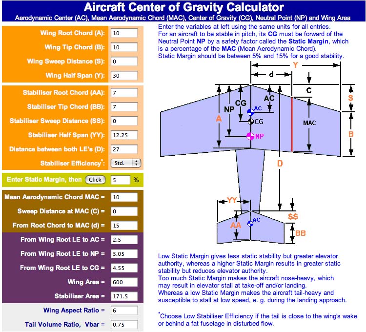
The online calculators use the Neutral Point, the AIRCRAFT'S aerodynamic center (AC), as a reference point to calculate the CG range. If the CG is placed on the neutral point (NP), the aircraft is considered to be "neutrally stable". Static Margin (SM), based on a percentage of the MAC, provides a CG location forward of the neutral point (NP) to enhance the longitudinal stability. The author of cg_calc stated that conventional designs use a static margin of between 5% and 15% of the MAC forward of the neutral point (NP). Cliff Griffin, creator of cg_super_calc, noted that if the CG is located 5% in front of the NP, the plane is 'twitchy'. Twitchy means pitch sensitive. Griffin also stated that when the CG is set at 20% of the MAC forward of the NP, the plane feels "mushy". The data for the rectangular wing plan form was placed in the orange boxes of cg_calc. A static margin of 5% was input. 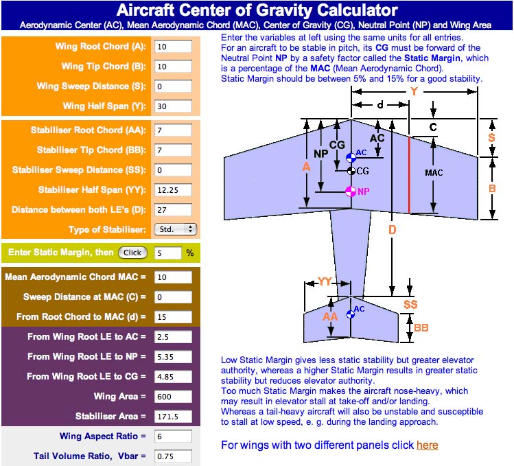
If the neutral point (NP) is 5.35" behind the leading edge (LE) of the MAC and the MAC is 10", the CG for a static margin of 5% is 5.35" (NP) - 0.5" (5% of a 10" MAC) or 4.85" behind the LE of the MAC. The plane will be "twitchy" at a static margin (SM) of only 5%. 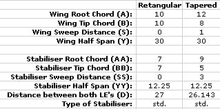 The online calculator inputs for the rectangular and tapered wing plan forms are shown in the table. 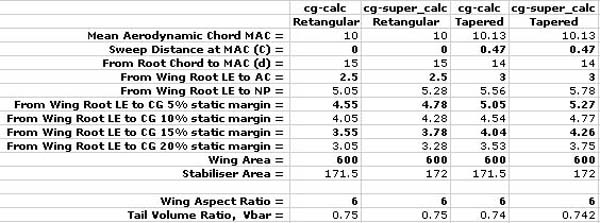 The calculators' results are shown in the table. The results for CG placements, with static margins (SM) of 5%, 10%, 15% and 20%, are shown for both calculators. The results vary due to the NP calculations by the two different calculator formulas. 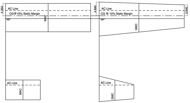 They say a picture is worth a thousand words. The numbers in the results table are somewhat difficult to visualize. The CAD drawing clearly shows the relationships using cg_calc data for a 10% static margin (SM). The line drawn through the neutral point (NP) of both plan forms demonstrates that it is in the same location on both plan forms. The dash dot lines show the CG at a 10% static margin. A solid line drawn between the CG lines of the two different plan forms makes it clear that the CG is in the 'same' location on both plan forms. If the 'finger method' is used at the tips to check the balance of the model, the rectangular plan form balances 4.35" from the LE of the tip if a 10% static margin is desired. Using the same method with a 10% static margin, the tapered plan form balances at 3.84" from the LE of the tip. A 10% static margin (SM) is not a good initial safe CG (ISCG). It is just used an example. Martin Irvine's column "Quiet Scale - CG Tips" references a formula attributed to Gordon Whitehead's book Radio Control Scale Aircraft - Models for Everyday Flying. CG = (Av. Chord / 6) + ((3 x Tail Mom. x Tail Area) / (8 x Wing Area)) Rewritten to the nomenclature used here it becomes: CG = (wing MAC / 6) + ((3 * Tail Moment (AC to AC) * horizontal tail area) / (8 * wing area)) Rectangle plan form: (10 / 6) + ((3 * 26.297 * 171.5) / (8 * 600) = 1.6666667 + (13529.807 / 4800) = 1.6666667 + 2.8187097 = 4.4853764 from the LE of the MAC or about 44.9% of the MAC The tapered plan form, using the same formula, places the CG at 4.507543" from the LE of the MAC or about 44.5% of the MAC. Using either of the online calculators' neutral points (NP), the static margins produced by Whitehead's book formula are less than 10%, which is marginal for both wing plan forms. 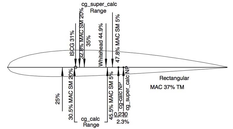
A Bit More on CG: In Rcadvisor's Model Airplane Design, Carlos Reyes said, "In a conventional aft-tail configuration, a good place to put the center of gravity if 30% back from the leading edge of the mean aerodynamic chord (MAC). For a trainer, make it 25%." Roy Day said in his article "Get the CG Right", "Now mark the 25 percent point on the MAC... Balance your plane at this point." Tim McKay, in his article "Designing Your First Model Airplane" said, "For a constant chord wing, locate the center of gravity 28 percent (0.28 x Wing Chord) back from the wing leading edge for initial flights." Note that the word initial was not underlined and in bold print in the original text. It was done in this context because it is a clue word. The 20% static margin (SM) points shown on the airfoil profiles for the rectangular and tapered wings for both calculators are rearward of the 25% MAC to 30% MAC mentioned by Reyes, Day and McKay. Martin Irvine alluded to an initial safe CG in his article. His example plane was a Japanese "Judy" Bomber. The preponderance of his article illustrated how to use the formula found in Whitehead's book. He calculated the CG, using that formula, at 4.7" from the leading edge of the MAC. The MAC was noted as 11.875". That placed the CG at about 39.5% of the MAC.
He then stated, "I must confess that I would probably start a little ahead of this, perhaps 4" from the leading edge (of the MAC KM) but plan to move it back with the motor pack." 4" / 11.875" = 0.337 or 33.7% of the MAC. 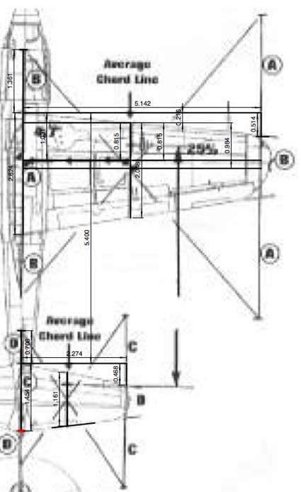
A CAD drawing of the plane in Martin's article yielded the inputs for the online calculators. 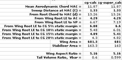 The differences in the positions of the NPs from each other are 4.4% of the MAC. 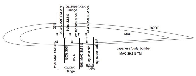 Whitehead's book formula does not appear to yield consistent results when compared to the rectangular and tapered plan forms. The calculators' static margin range of 5% to 20% appears to yield dissimilar results because the neutral points (NP) are calculated to be in different positions. The 15% static margin of cg_super_calc is approximately where Martin Irvine said he would place the CG for the initial flight. Using cg_calc Martin's point has a static margin of about 10%.
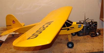
The Thunder Tiger Lazy Tiger Cub is unconventional in that it has a low aspect ratio wing and a relatively short tail moment. Before the first flight, the Lazy Tiger Cub's CG was checked and found to be near the manufacturer's rearmost suggested CG. It was at 3-3/4" from the wing's leading edge (LE). According to the Thunder Tiger instruction manual, "Your Lazy Tiger Cub should balance 3-1/2" (26% of chord) to 3-3/4" (28% of chord) back from the leading edge of the wing (about 3/8" in front of the main spar.)" The first flight did not go well. There were several 'issues' with the plane. One of the 'issues' was definitely the CG. A CG dive test was performed. The plane started a 1/2 outside loop during the dive test. The CG dive test indicated that it was extremely tail heavy. A How To and What the Results Mean How: (It is best to do this test on a close to windless day and into the wind. It must be performed so that observations can be made as to what is happening.) 1. Trim the plane for level flight at cruising speed
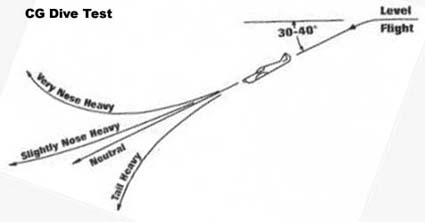
Martin Irvine's Graphic What the observations mean: 1. If the plane continues in a straight line, it is neutrally stable
For more information on the CG Dive Test see Keith Shaw's "The Art of Low Power Aerobatics". The battery pack of the Lazy Tiger Cub and the ESC were moved as far forward as possible. The result was that the CG shifted to 3-3/8" (3.375") from the leading edge. That is 25% of the MAC or at the wing's aerodynamic center (AC). Some of the other issues with the plane were corrected. The CG dive test was performed and the plane was found to be neutrally stable. With the CG at 3-3/8" (25% of the MAC), it was still slightly pitch sensitive, but usable as a trainer. 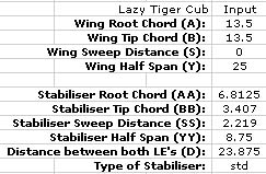 The Lazy Tiger Cub input data for the online CG calculators. 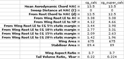 The results from the calculators demonstrate that there is a 4% of the MAC difference between the calculations of the NP positions. The plane was almost 'unflyable' when the CG was at 3.75" or only 27.8% of the MAC. 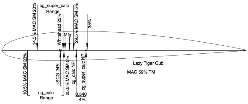
Another Unconventional Conventional Design
In the spring of 2008, Dereck Woodward designed a low aspect ratio wing, short tail moment plane that he called the VSP for Very Short Plane. It was published in Fly RC in the March 2011 issue. 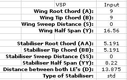 The VSP input data. 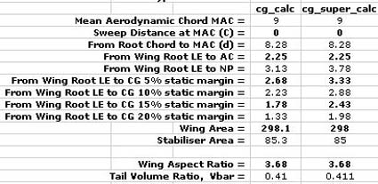 The results from the calculators show a 7.2% of the MAC difference between the calculations of the NP positions. The two calculation programs imply that Dereck's suggested CG of 3" provides a static margin described as twitchy. RC Groups member RBCCONT indicates that he set his initial CG at 2-7/8" or 31.9% MAC. Video of RBCCONT's maiden flight. The plane appears "twitchy" in the video (could be the wind) and the end result is a crash. A second video, on a day with less wind, shows the plane to still be a bit pitch sensitive even though RBCCONT noted that he had removed some of the tail weight. 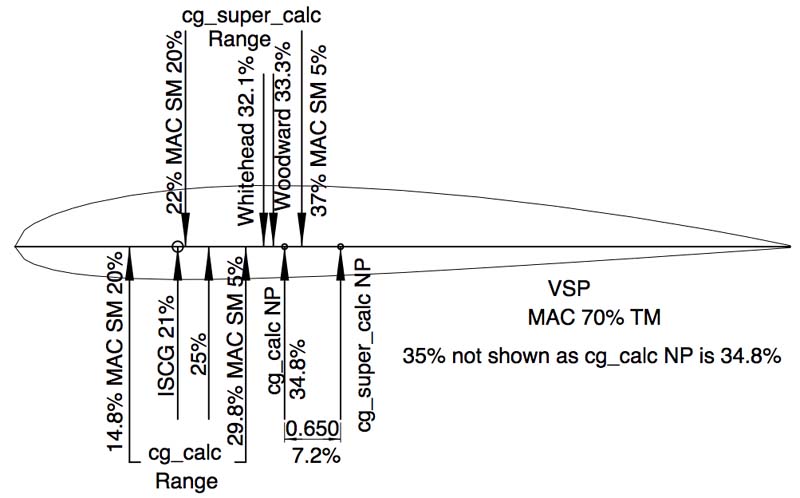
The Same Plane in Two Scales The ElectroFlying Fusion and the scratch-built Fusion 380 have the same proportions. 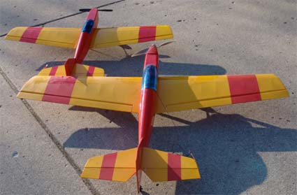 Steve Pauley, the designer of the ElectroFlying Fusion suggested an initial balance point of 2-7/8" (2.875") from the LE edge. The MAC is 10.189" and 2-7/8" is 28.2% of the MAC. The wing plan form is different from the preceding plan forms. It has a straight leading edge and tapered trailing edge. 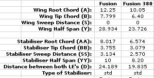 The Fusion Inputs are shown above. 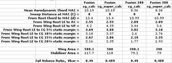 Whitehead's formula suggested a CG placement of 3.477" from the LE of the MAC, which is 34.1% of the MAC. Steve Pauley's recommendation proved to be correct for the ISCG on both planes. 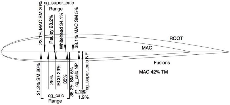
Flite 40 ARF Low-wing From Dymond Modelsport Ltd.
The Flite 40 has a rectangular low-wing plan form with a tapered horizontal tail and quite a long tail moment. It was initially flown with the CG at 3-5/8" inches or 31.5% of the MAC. 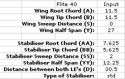 The Flite 40 input data is shown above. 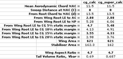 The Flite 40 results show a difference of 6.8% of the MAC between the two calculators. Whitehead's book formula suggested a CG placement of 4.88" from the LE of the MAC, which is 42.4% of the MAC. 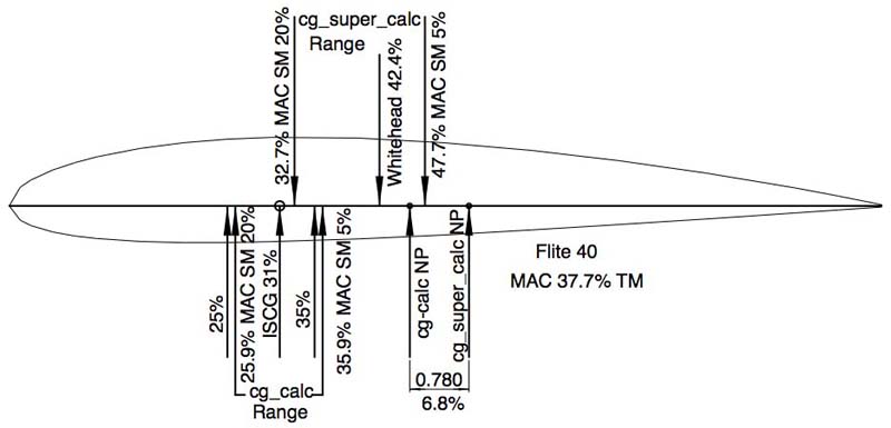
Analyzing the data to find an initial safe CG Other Factors The choice of an initial safe CG is critical, but there are other factors that influence longitudinal stability. The airfoil chosen for the wing and horizontal tail have an affect. The angles of incidence for the wing and horizontal tail create the longitudinal dihedral or decalage (LD), which also has an effect on the longitudinal stability. While those influences affect how well the plane flies, the correct ISCG is the dominant factor for 'survival' during the maiden flight. The Thunder Tiger Lazy Tiger Cub prompted the investigation into the initial safe CG. Flight-testing determined that the manufacturer's CG recommendations were suspect. Even though the rearmost recommendation was only 27.8% of the MAC and the foremost 26% of the MAC, they were not 'good' recommendations. The plane was 'flyable' with the CG at 25% of the MAC, but the rearmost manufacturer's CG recommendation yielded an almost 'unflyable' plane. It was EXTREMELY pitch sensitive. The airfoil profiles, showing the various recommended CG positions, were printed and compared. A printable foils profile .pdf.
The online calculators impart an impression of accuracy, but their results are not similar enough, through all of the examples, to support an acceptable and logical initial safe CG placement. The positioning of the neutral point fluctuates greatly between the two online calculators and creates different results. The formula from Whitehead's book yields approximately the same CG position as 25% of the MAC for the Lazy Tiger Cub but the formula can produce a recommended CG at close to 45% of the MAC, which it does for the rectangular plan form. The positioning of the CG using the formula from Whitehead's book also changes significantly. 33% to 35% of the MAC on the Lazy Tiger Cub was definitely not an ISCG! Nor does it appear to be an ISCG for the VSP. Even the traditional 33% of the MAC 'hops' around compared to the neutral point. If either of the online calculators is to be believed, the 33% MAC point may end up behind the neutral point (NP). That would not be good. Roy Day's 25% of the MAC certainly appears to provide an ISCG except for two problems. Planes with short tail moments (i.e. Lazy Tiger Cub & VSP) may be somewhat 'twitchy' with the CG set at 25% of the MAC. The NP is relatively further forward and the static margin is smaller. The shorter the tail moment, the further forward the NP is. The further forward the NP is, the less 'room' there is for the static margin (SM). The less the SM, the 'twitchier' the plane is. Planes with long tail moments (Flite 40) with the CG set at 25% of the MAC may be too 'mushy' and not have enough elevator 'authority' upon landing. The NP is relatively rearward and the static margin is larger. When using the traditional 25% of the MAC CG, even the more traditional layouts appear to have a greater static margin than is necessary for a safe maiden flight, no matter which of the online calculators neutral points is used. Still looking for a better solution for the initial safe CG, another CG formula, by Martin Simons, was found. 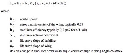 The formula appears to be too 'complicated' for the modeler who only wishes to know if the RC plane is going to survive the initial flight so that it may be adjusted to the pilot's preferences and the mission's requirement. A New Hypothesis The following is a hypothesis for selecting an initial safe CG. The wing and horizontal tail MACs and ACs are required and the tail moment (TM) defined as wing AC to horizontal tail AC. The ISCG shown on the airfoil profiles was created using this hypothesis. Step 1: Determine the MAC and AC for the wing and horizontal tail. Step 2: Determine the tail moment distance AC to AC Step 3: Divide the wing MAC by the tail moment. The result shows the MAC as a percentage of the tail moment (TM). Round to the closest percent. MAC / TM Step 4: Use the table to determine the initial safe CG as a percentage of the MAC. 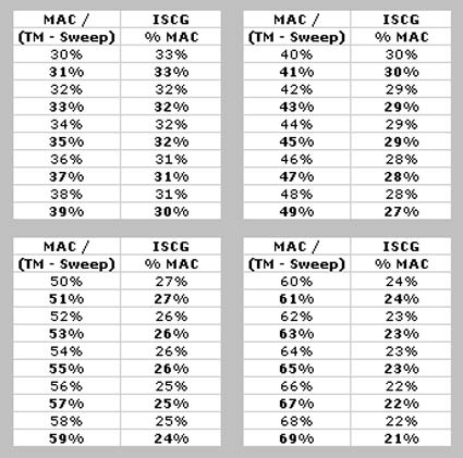 The initial safe CGs for the example layouts: Rectangular: MAC 10", tail moment 26.297"
Tapered: 10.133 / 26.297 = .38.5, 39% = ISCG 30% MAC = 3.04" = 3" from MAC LE "Judy" Bomber: 11.875 / 29.8 = .398 = 40% = ISCG 30% MAC = 3.5625" = 3-9/16" Lazy Tiger Cub: 13.5 / 22.874 = .59 = 59% = ISCG 24% MAC = 3.24" = 3-1/4" VSP: 9 / 12.921 = .69.7 = 70% = ISCG 21% MAC = 1.89" = 1-15/16" ElectroFlying Fusion: 10.189 / 24.365 = .418 = 42% = ISCG 29% MAC = 2.955" = 3" (Mfg. recommendation 2-7/8") Fusion 380: 8.36 / 19.979 = .418 = 42% = ISCG 29% MAC = 2.42" = 2-7/16" Flite 40: 11.5 / 30.243 = .38 = 38% = ISCG 31% MAC = 3.565" = 3-9/16" The fractional inch to decimal table was used to convert the decimal inch numbers into fractional inch numbers. 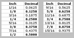
Fractional Inch to Decimal Table Use 25% of the wing MAC if the wing MAC divided by the tail moment is 50% or greater. Use 30% of the wing MAC if the wing MAC divided by the tail moment is less than 50%. This article was started on September 27, 2011. Data was gathered using the two online CG calculators and recorded in an Excel worksheet. At various times during the next month the data was checked and double checked for errors. There was a question about some data on October 21, and the input numbers run in the cg_calc program. The data appeared to be correct. The airfoil profiles with their data were printed on October 23, 2011 to compare the various formulas to find an ISCG. The online calculator cg_calc was used to check the Lazy Tiger Cub data one more time. The results had changed. The results no longer matched the data on the worksheet or drawings. All of the inputs were double-checked and found to be correct. All of the cg_calc results, for all of the example planes, were verified one more time. They had all changed! The cg_super_calc data remained the same for all the examples. Something had happened to 'change' the formulas and the results in cg_calc! The new results data was input into new results tables for each example and new airfoil profiles with the new CG data were created! It was very time consuming for unexplained phenomena! The following is a screen capture of cg_calc before October 23 and another taken on October 23 showing the varying results.
Screen Capture September 30, 2011
All of the inputs are the same but the NP was calculated as 5.35 before October 23 and at 5.05 on the 23rd. The 5% static margin (SM) CG moved from 4.85 to 4.55. References: Roy Day, "Model Airplane News", September 1998, "Get the CG Right" Keith Shaw, "Tech-talk to the EMFSO", March 1992 Martin Irvine, "Electric Flight International", April 2001, "Quiet Scale Đ CG Tips" Gordon Whitehead, Radio Control Scale Aircraft - Models for Everyday Flying Author of Web site "Welcome to Model Aircraft" Carlos Reyes, Rcadvisor's Model Airplane Design, copyright 2009, Cliff Griffin?, "Aircraft Super Calculator 7.5.1" Tim McKay, "Designing Your First Model Airplane", p.30-32, Fly RC, January 2012 Dereck Woodward, VSP - Very Short Plane |