An Introduction by Frank Siegert (Graduate Engineer) June 2015 Originally translated into English by John Julian
HTML version and American English sentences and/or clarifications by Ken Myers
Forward by Ken Myers
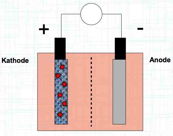
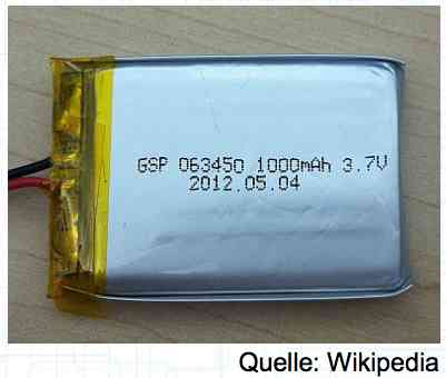
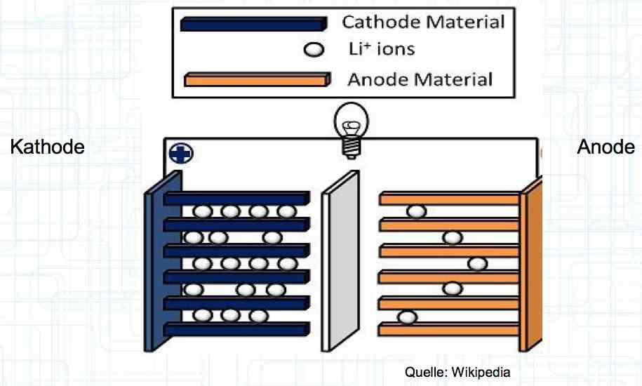
Special thanks to Dave Stacer, friend and flying buddy, for his assistance in proofing and formatting this document. 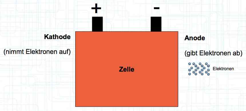 The illustration shows the exterior of a Lithium Polymer Pouch (LiPo) cell (Zelle). The Cathode (Kathode) is said to accept electrons and the Anode to give up, or lose, electrons. The little blue dots in the lower right corner of the illustration represent electrons. 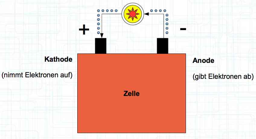 An external view of a cell, during discharge, shows that the electrons (the little blue dots) are said to be moving from the Anode to the Cathode. 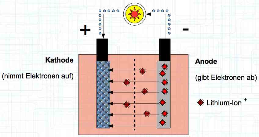 Inside the cell, during discharge, the Lithium Ions are moving from the Anode to the Cathode. Electrons flow 'outside' the cell and Lithium Ions inside the cell. For Electrons, the cell is a non-conductor. 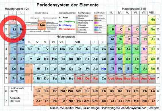 The Periodic Table shows that Lithium, after hydrogen and helium, is the lightest element. Lithium is an alkali metal with three protons in the nucleus and three electrons in the outer shell.
The cell strives to reach the state of "lowest energy". This is (theoretically) achieved when the cathode is replenished with lithium. 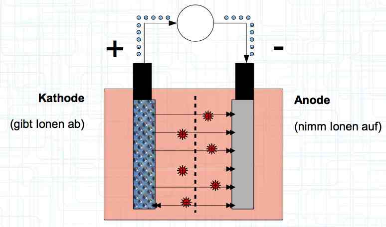 During charging, positively charged Lithium ions move from the Cathode to the Anode, which accepts them. Also, during charging, electrons flow from the cathode to the anode.
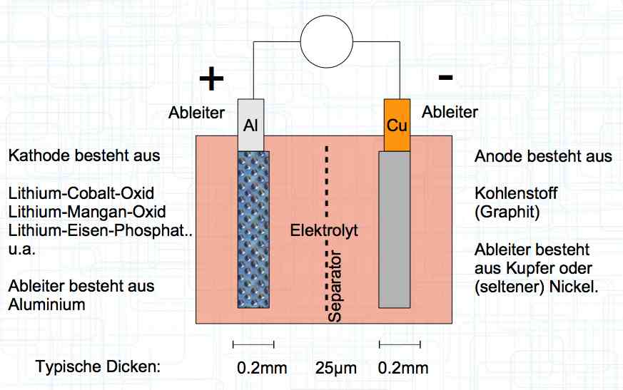
The cell has a positive (+) Aluminum (Al) terminal and negative (-) Copper (Cu) terminal.
At 1 amp of current for every second there flows 6.2 x 10¹⁸ positive Lithium Ions through the cell.
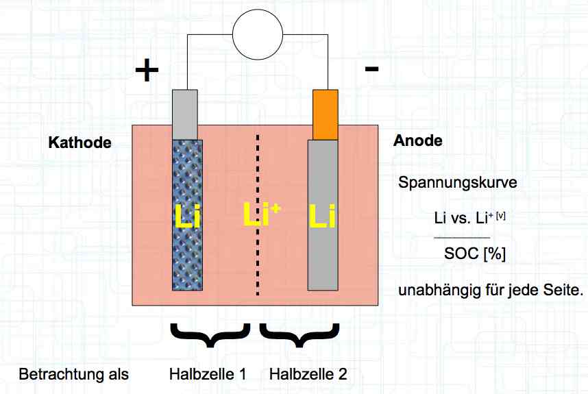 The voltage curve is independent for each side of the cell. SOC means state of charge and is represented as a percentage of a full charge. Halbzelle means half of the cell. 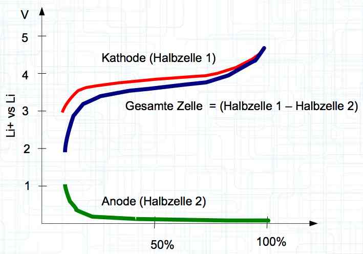 The graph illustrates the voltage curve theory. There are lines for the Cathode (Half-cell 1), Total cell (Gesamte Zelle) = (Half-cell 1 and Half-cell 2) and Anode (Half-cell 2).
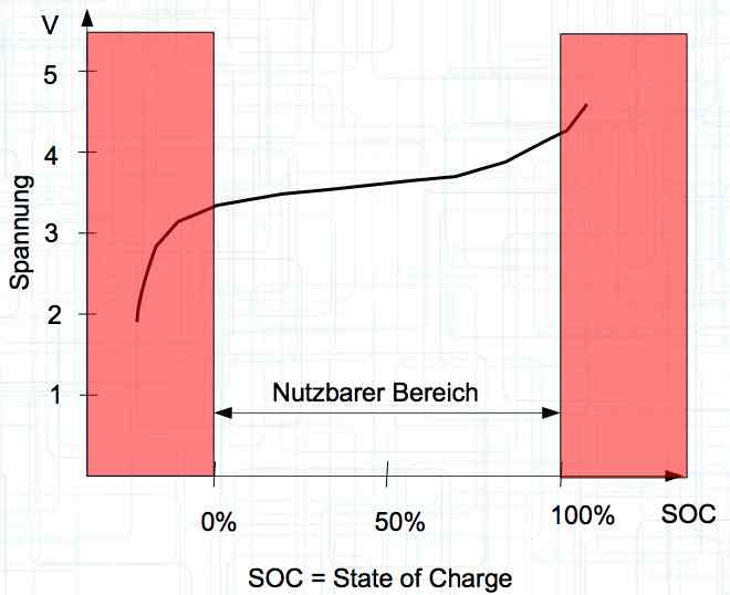
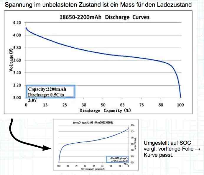 Voltage, in the unloaded state, is a measure of the charge status. With the graph shown above flipped horizontally (shown by the small graph below the larger graph), the smaller graph is changed to a graph showing the state of charge (SOC). The curve then fits the pervious graph showing the voltage curve.
Damage can be done to the cell if it is discharged to too low of a voltage or charged to too high of a voltage outside the usable area. Nutzbarer Bereich means the usable area.
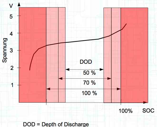
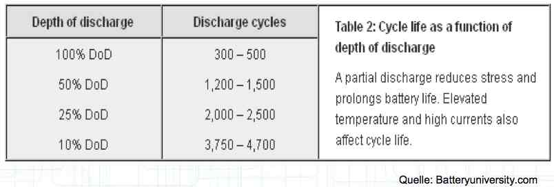
The utilization rate of the maximum capacity available. Depth of Discharge Aging
The maximum utilization of the cell yields the minimum lifetime. The above figures are for about a 1C discharge rate. High-current discharges lead to a greatly reduced cycle life by accumulation of damage in the cell. The Maximum current drain yields the minimum lifetime.
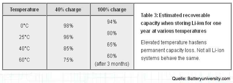
0°C = 32°F: 25°C = 77°F: 40°C = 104°F: 60°C = 140°F Deterioration, due to aging, depends on the storage voltage (the higher the voltage the faster the aging) and storage temperature (the higher the temperature the faster the aging). The total life depends on cycle aging caused by damage in the cell by charging and discharging and storage-aging causing damage in the cell.
The effects of aging are a decrease in capacity, increase in internal resistance, a decrease in current capability, and a decrease in the maximum possible charging current.
A Pouch Cell is layered or wrapped in a plastic 'bag' and filled with electrolyte. 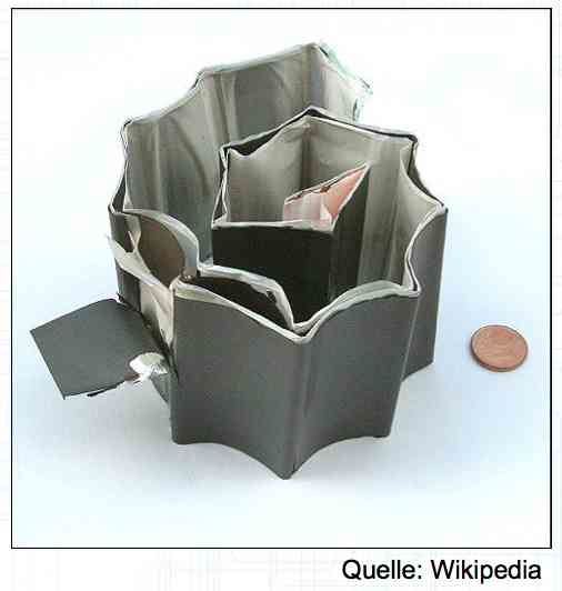 The physical construction consists of thin layers, wrapped, folded or 'stacked' for maximum surface area. 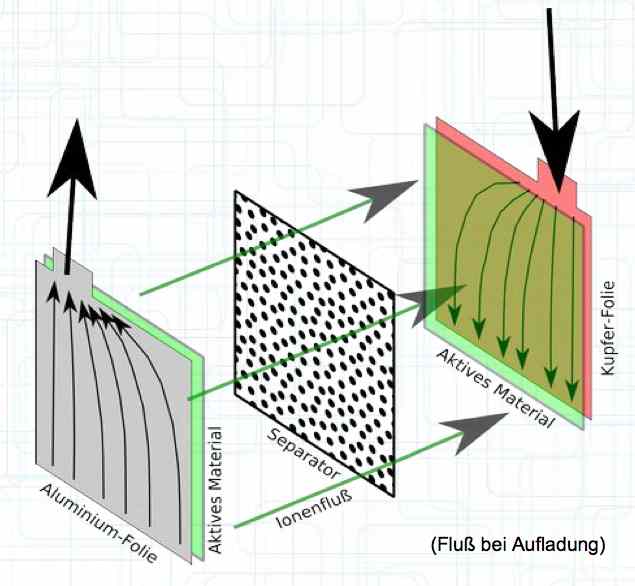 When charging, the electrons flow from the Cathode to the Anode and the positive Lithium ions move from the Cathode active material through the separator to the Anode active material. It is important to note that the current flow in the cell is not equally distributed, but focuses near the terminals. The heat development of the cell during charging and discharge is composed of two elements:
For high-current applications, the irreversible heat generation dominates, especially during discharge.
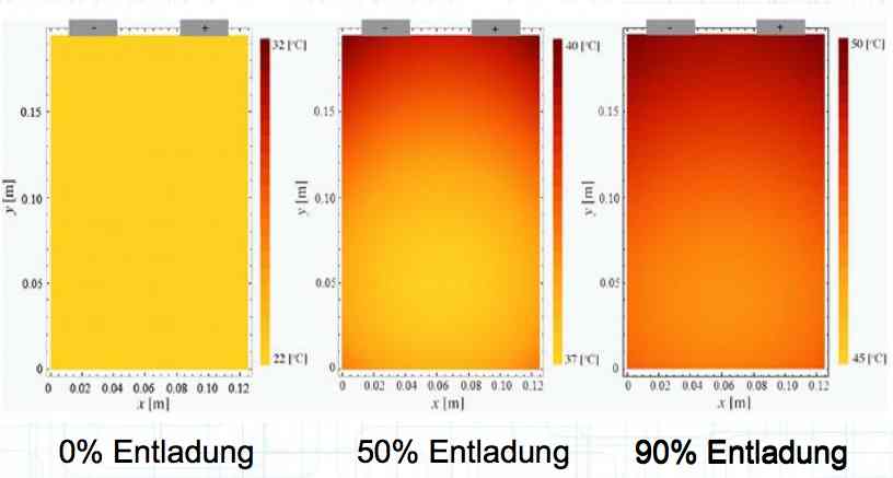
 Entladung means discharge. Irreversible heat generation in the cell at a high current discharge is not equally distributed, but localized near the terminals, as shown in the illustration. Because of this unequal heating, cells do not age uniformly. There is a higher load area. Also, cells in a pack do not age uniformly. Internal cells cannot dissipate their heat as well. 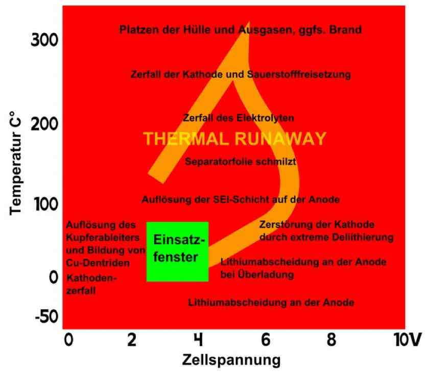 The illustration shows the temperature versus the cell voltage. The green box is the "Application Window", where the cell is best used. The wording on the left of the box says, "Formation of copper (Cu) deposits and Cu dendrites causes Cathode disintegration." The rest of the wording - top to bottom: "Bursting of the cell and outgassing, if necessary. Fire." "Disintegration of the Cathode and volatiles released." "Decomposition of the electrolyte" THERMAL RUNAWAY "Separator film melts." "Disintegration of either layer on the Anode." "Destruction of the cathode through extreme delithiation" "Lithium deposition on the Anode at high currents" "Lithium deposition on the Anode" Positive electrode (cathode): Lithiated form of a transition metal (eg, Lithium Cobalt (III) oxide LiCoO2, Lithium Nickel Oxide LiNiO2 or Lithium Manganese oxide LiMn2O4) and mixed forms. Negative electrode (anode): Carbon (C), usually graphite (C6) Electrolyte: Lithium salts (LiPF6, LiBF4, LiClO4) and organic solvents (Ethylene Carbonate, Dimethyl Carbonate, etc.)
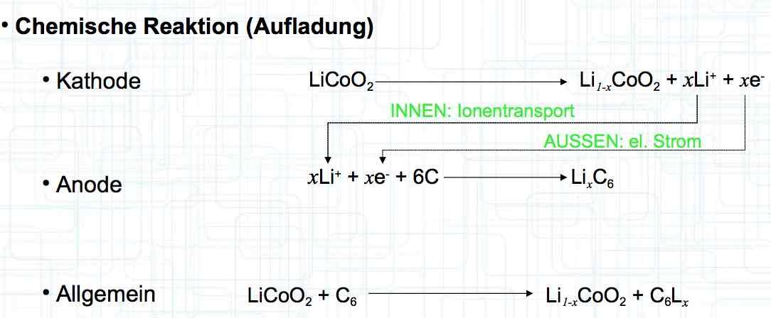
The diagram illustrates the chemical reactions during charging. It illustrates the reactions at the Cathode, Anode and Overall (Allgemein). INNEN: Ionentransport is INTERIOR: ion transport AUSSEN: el. Strom is EXTERIOR: electric current The Cathode loses lithium during charging, the anode is filled with lithium. Intercalation
 The diagram once again illustrates the makeup of the cell. The cell performance depends on:
Capacity:
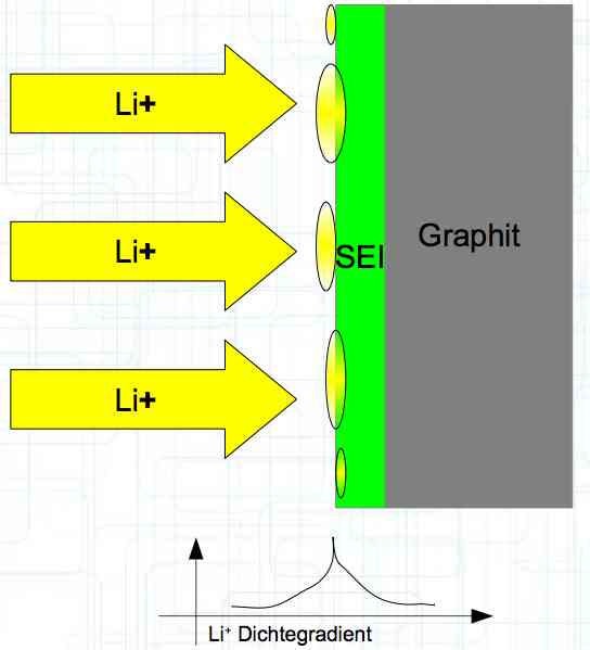
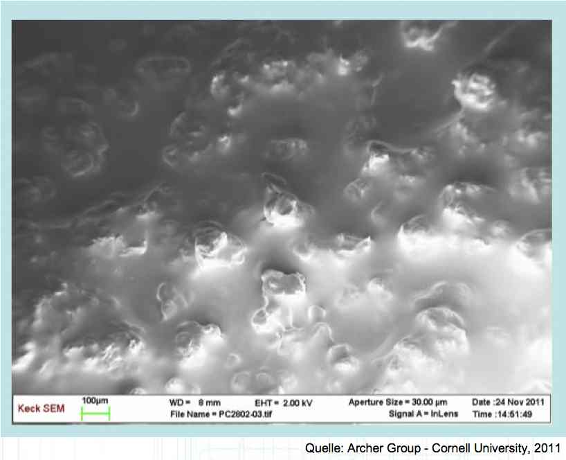
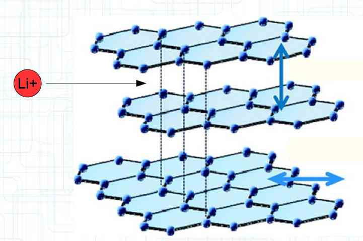 The graphite anode consists of layers. Ions can only penetrate "from the side". This yields a charging rate that is generally lower than the discharge rate. (inwards is worse than outwards) 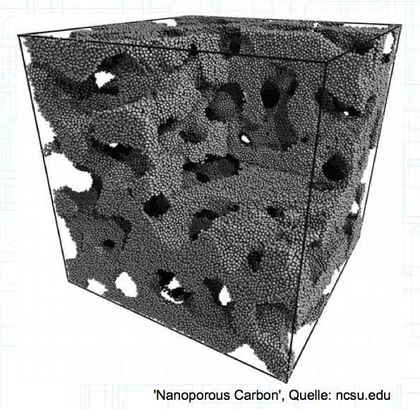 The photo demonstrates "Nanotechnology". When using nanotechnology, the graphite layers, with finer ("nanoporous") structure, yields a larger active surface. 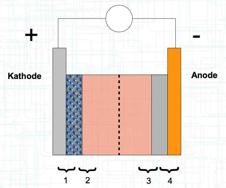 There are four transition zones shown in the diagram. The most relevant are Zone 2, between the cathode and electrolyte and Zone 3 between the electrolyte and anode. The latter, in particular, is extremely important for the function of the cell. 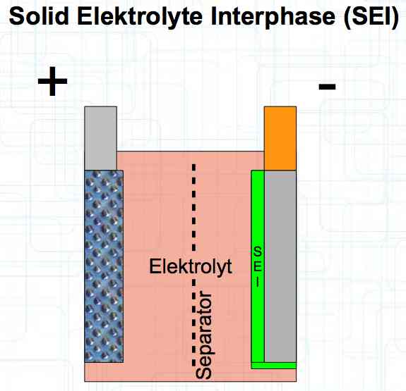 The solid electrolyte interphase (SEI) layer protects the graphite anode. The graphite anode would be destroyed by reactions with the electrolyte without it. To stop this process, a protective coating has to be applied on the carbon. This layer is called the solid electrolyte interphase (SEI) layer. 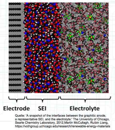 The SEI layer is composed of the electrolyte and the anode in the initial formation (first charge during the manufacturing process). Lithium ions must penetrate it during charging and discharging. The SEI-Layer provides protection and stabilization of the anode. Without an SEI layer there is no cycle stability. The SEI layer is basically constructed in the preparation of the cell. Any cell which is 'new' has already experienced at least one preparation cycle.
 The deposition of metallic lithium ions at the anode, when charging, is called plating.
Plating occurs when 'the anode wants more Li+ ions in' than can be accommodated with the transportation capacity available.
 The Lithium plating does not form in clean 'layers' but in "towers" called dendrites. 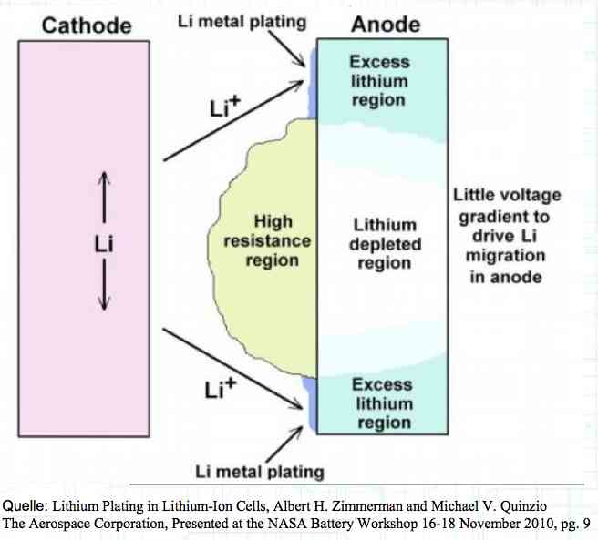 The plating is also caused by "flaws". 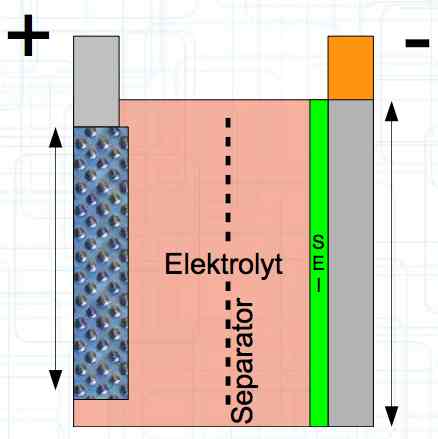 Also, in production, the anode is always designed to be somewhat larger than the cathode, otherwise, at the edge, zones plating would occur. This excess material on the Anode is referred to as "Overhang". 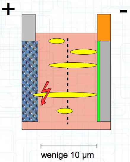 Plating causes Lithium loss and Lithium dendrite formation if the separator is bridged. This condition is called a "Micro Short". wenige 10 μm means a few 10 microns 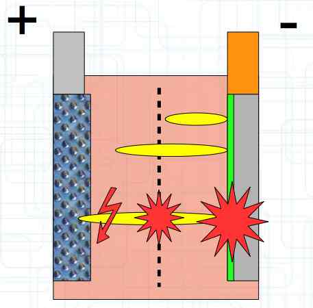 "Micro Shorts" can become "Macro Shorts" if there is an extreme local temperature increase, the separator is damaged, or there is local collapse of the SEI layer causing an exothermic reaction. The resulting defect leads to further plating. 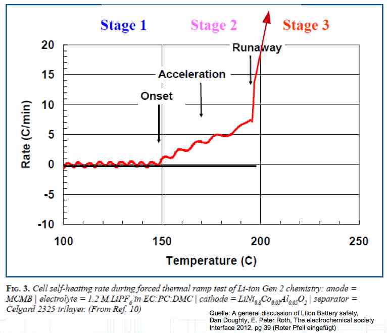 Thermal Runaway occurs from about 150°C (302°F) when the "Self-heating rate" is greater than 10°C (50°F) per minute. 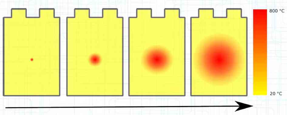 Thermal runaway starts around 150°C (302°F). The heat build-up to the 'Onset' is primarily based on resistive heating by the "Short", to about 250°C (482°F), then it becomes a significant exothermic decomposition processes. If the runaway temperature is reached locally, and the affected area is sufficiently large, it spreads very quickly through the entire cell. 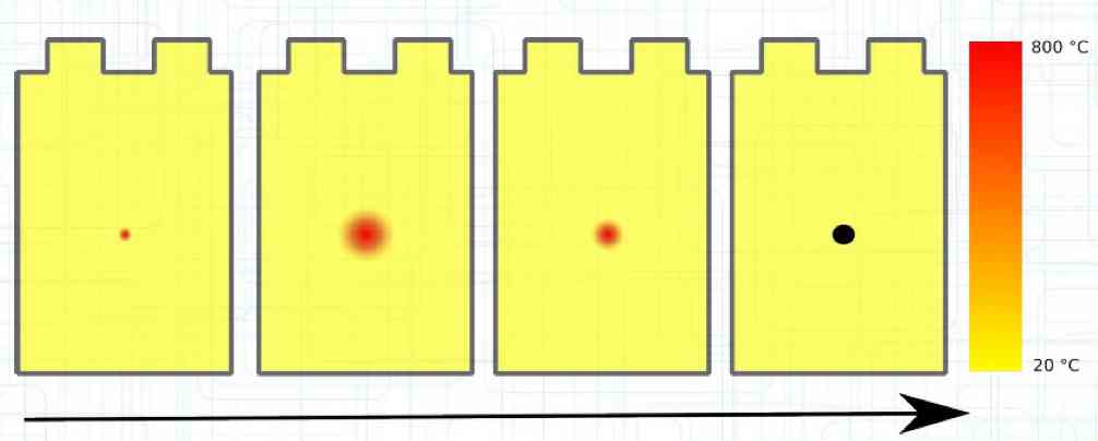 If there is not sufficient heat generation, then the result is only a void. The self-limitation occurs in part because the separator expands when heated and thereby locally lowers its ion conductivity. As long as the separator does not melt, the short circuit will be limited. However, this fault can possibly act as a trigger for further plating. The temperature rise to 'Onset' can also occur slowly (minutes to hours). Once this is achieved, however, the heating occurs faster locally.
A cell must have sufficient energy stored for a runaway. The higher the SOC, the more likely it is.
Factors for the formation of plating include high charging current, low temperatures (while discharging), old or overloaded cells with a thick SEI layer, flaws from manufacturing defects or damage, or too high of a discharge current. (See explanation of the Cathode.)
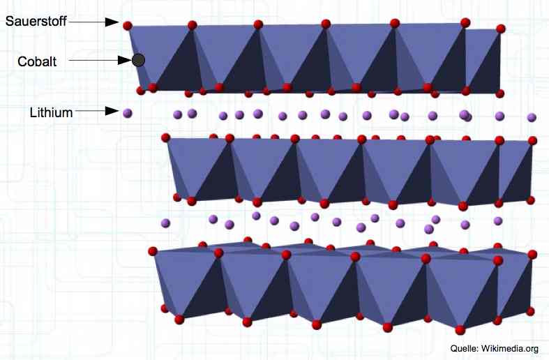 The Cathode consists of Lithium Metal Oxides, such as LiCoO2. The diagram shows Oxygen (Sauerstoff), Cobalt, and Lithium. When charging, the positive lithium ions move from the cathode to the anode.
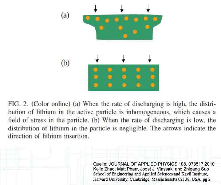 At high discharge rates, the cathode is under mechanical stress. 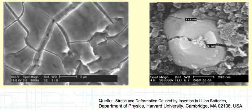 High discharge rates, especially at low temperatures, leads to cracks and fractures in the Cathode. Advice: Never overload cold cells! COLD CELLS is NOT defined in the document. It is 'hinted' at in the section "Cell Failures and Their Causes/Temperature Related Failures" where it says, "If the cell temperature is too low, less than 15°C (59°F)...  Temperatures that are too high, even locally, and/or cell voltage greater than 4.1V causes a reaction process (oxidation) of the electrolyte at the cathode layer. The reaction products are deposited primarily on the SEI layer at the anode. This process causes an increase in the internal resistance and the loss of capacity. These reactions also produce gases (mostly CO2). The gasses are the main reason for irreversible "puffing" after an overload or storage at a fully charged state (especially at high temperatures). 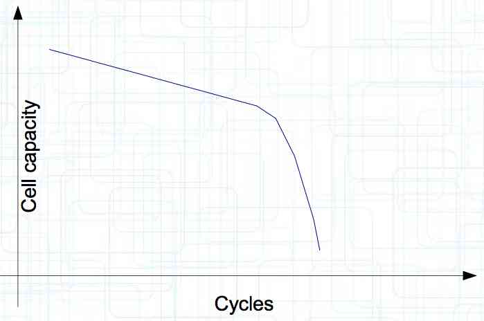 Accumulation of the oxidation products on the SEI Layer is the main reason for the 'kink' in the loss of capacity curve shown in the graph above. This goes hand in hand with an increase in the associated internal resistance. 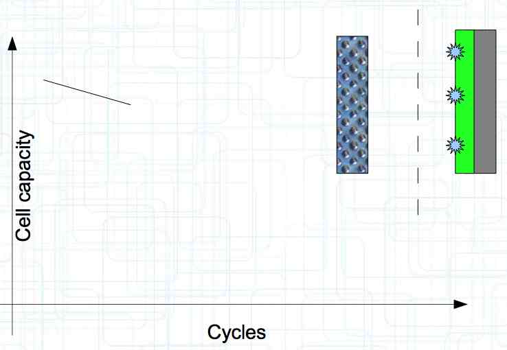 Initially there is minimal effect on the capacity as the SEI surface is sufficient. 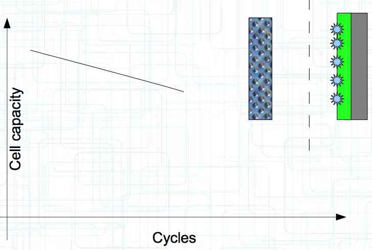 Increasing the effect, the SEI surface is still just enough.  At the start of accelerated aging, the internal resistance has increased significantly, plating sets in, and the lithium loss becomes relevant. 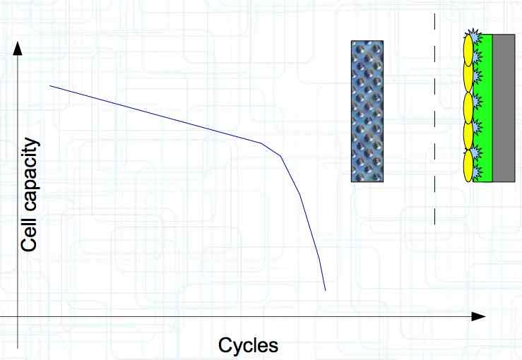 Once the plating is dominant, the Lithium loss is high. The cell clearly loses capacity, while strongly increasing its internal resistance. Advice: Do not overload/overburden the cells. 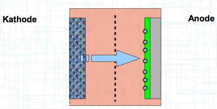 Excessive temperatures lead to the release of free "metals" at the cathode. This causes "poisoning" of the SEI layer This is a problem mainly in LiFePO4 cells as it triggers iron deposition at temperatures greater than 45°C (113°F). Advice: Do not store cells in a warm environment!
Cell damage accumulates over the period of use. A cell does not forget mistreatment! 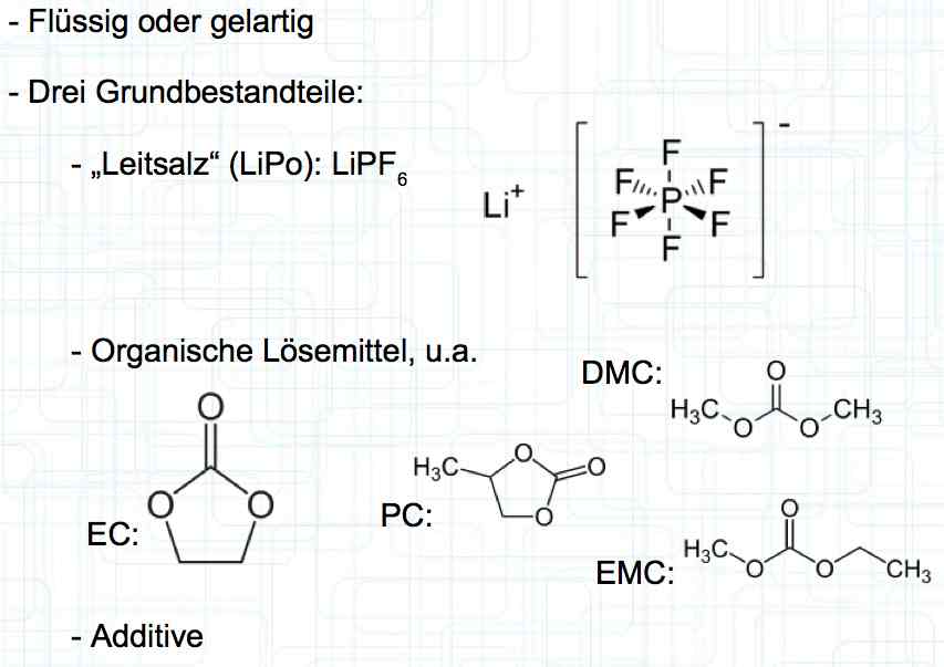 The electrolyte can be in the form of a liquid or gel. There are three basic components of the electrolyte; "Electrolyte salt" (LiPo), LiPF6, organic solvents, including EC, PC, DMC, EMC, and additives. 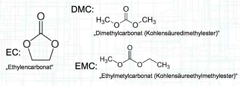 The mixing ratio of the organic solvent determines whether, at room temperature, it is more liquid or gel-like. EC is Ethylene Carbonate DMC is Dimethyl Carbonate EMC is Ethyl Methyl Carbonate Simplified: The higher the EC share of the mixing ratio the more solid, and thermally stable at high temperatures, the electrolyte is. 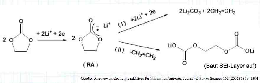 Ethylene Carbonate (EC) is always included in the mixture. It is necessary for the formation of the SEI layer on the Anode. It builds the SEI layer on the Anode. EC yields the SEI Layer that is formed in the first cycle. 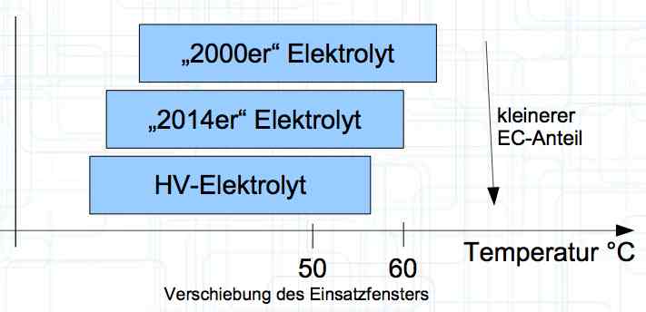 The mixing ratio determines the temperature and voltage capability. Using EC and DMC the electrolyte is unstable from about 4.25V. Using EC, DMC and diethyl (DEC) in a 3:3:4 ratio, the electrolyte is stable to 4.5V. The EC proportion has declined in recent years (From about 50% to about 25%). High Voltage (HV) cells have smaller proportions of EC in the electrolyte and are therefore slightly less temperature stable. The graph shows the changes between the year 2000 electrolyte and 2014 electrolyte and compares them to an HV electrolytic. There is a smaller EC-share from the year 2000 through the HV type. That has caused a shift in the usable temperature window. 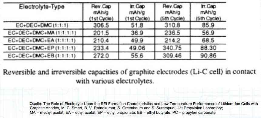 Depending on the electrolyte composition, the formation, after the first charge, is not yet fully completed. Advice: Gentle treatment of the cell in the first cycles may therefore be useful. Additives Additives are used to:
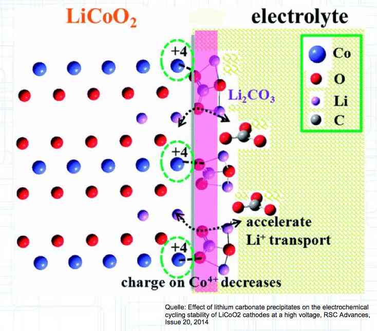 HV cells have improved cathode stability by using the additive Li2CO3. Failures Caused by Voltage Errors If the voltage is too high, greater than 4.25V, the Cathode has stress caused by extreme delithiation, the Anode suffers from lithium plating yielding Lithium dendrite formation and the Electrolyte decays due to the oxidation processes at the cathode. If the voltage is too low, less than 2V, the Cathode has stress due to high delithiation and Oxygen is released, the Copper carrier dissolves releasing oxygen and producing copper (Cu) dendrites on the Anode. Temperature Related Failures If the temperature is too high, greater than 60°C (150°F) (greater than 55°C (131°F) with newer type cells) the Cathode releases oxygen and the Anode has a SEI layer breakdown.
If the cell temperature is too low, less than 15-20°C (59-68°F) at a high C-rate, the Cathode is stressed from too high of a lithium-ion flow and breakage and cracks occur during discharge.
Discharge Rate and Charge Rate Failures If the discharge rate is too high, the Cathode suffers from oxidation of electrolyte (especially at high temp) and there is stress caused by the high lithium-ion flow. That stress causes breaks and cracks in the Cathode, especially at low temperatures.
If the charge rate is too high, and in particular at low temperature, the Anode suffers from plating. Cell Puffing Failures "Puffed" cells are divided into two different types: "Reversible" puffing occurs in a high-current discharge. The cell reforms after cooling back down. This is basic puffing caused by the evaporative components of the solvent in the electrolyte. It is a sign of a current overload, but cell can still be used. "Irreversible" puffing does not reverse after cooling. Its basic cause is the decay processes of the electrolyte forming CO2 and other gases. It is an indication of defects in the cell. The consequence is a loss of capacity and increased internal resistance. If a deep discharge occurred, immediately discard cell. There is probable damage to the cathode, which was accompanied by oxygen release.
Damaged cells smell 'sweet' or 'fruity' if electrolyte leaks. Such cells must be disposed of immediately. Only hold them with protective gloves, as the conductive salts in the electrolyte are poisonous and corrosive. Some additives are dangerous as well. Conducting salts ("LiPo") LiPF6:
Conducting salts ("LiFePo") LiBF4:
Store cool, dry and empty (about 3.7V per cell) at or less than 20°C (68°F)
Even longer life:
Credits
References / Quellennachweise: Seite 6: Illustration: Wikipedia, Quelle: https://commons.wikimedia.org/wiki/File:PSE.png Seite 7 und 8: Tabellen: Battery University, Quelle: Seite 21 und 22: Bilder Lithium Pouch Cell, Quelle: Seite 25: A Distributed Analytical Electro-Thermal Model for Pouch-Type Lithium-Ion Batteries
Seite 30: File:Schematic of a Li-ion battery.jpg, Public Domain,
Seite 33: Nanoporous Carbon, Development of Improved Molecular Models of Amorphous Nano-porous Materials, Gubbins Group,
Seite 36: : 'A snapshot of the interfaces between the graphitic anode, a representative SEI, and the electrolyte.' The University of Chicago, Searle Chemistry Laboratory, 2012,Martin McCullagh, Ruibin Liang, Seite 41: Archer Group, Electrochemical Energy Storage, Dendrite propagation, 348 Olin Hall Cornell University, Ithaca, NY 14853, https://archergroup.cbe.cornell.edu/dend_grw.html Seite 42: Lithium Plating in Lithium-Ion Cells, Albert H. Zimmerman and Michael V. Quinzio The Aerospace Corporation, Presented at the NASA Battery Workshop 16-18 November 2010, pg. 9 Seite 46: A general discussion of LiIon Battery safety, Dan Doughty, E. Peter Roth, The electrochemical society Interface 2012. pg 39 (Modified: Red arrow inserted, Verändert: Roter Pfeil eingefügt) Seite 52: File:Lithium-cobalt-oxide-3D-polyhedra.png, Public Domain, Seite 54: Effect of Ion flow on cathode. Journal of applied Physics 108, 073517 2010, Kejie Zhao, Matt Pharr, Joost J. Vlassak, and Zhigang Suo, School of Engineering and Applied Sciences and Kavli Institute, Harvard University, Cambridge, Massachusetts 02138, USA, pg 2 Seite 55: Stress and Deformation Caused by Insertion in Li-ion Batteries, Department of Physics, Harvard University, Cambridge, MA 02138, USA Seite 66: A review on electrolyte additives for lithium-ion batteries, Journal of Power Sources 162 (2006) pg. 1379 Seite 68: The Role of Electrolyte Upon the SEI Formation Characteristics and Low Temperature Performance of Lithium-Ion Cells with Graphite Anodes, M. C. Smart, B. V. Ratnakumar, S. Greenbaum and S. Surampudi, Jet Propulsion Laboratory; Seite 70: Effect of lithium carbonate precipitates on the electrochemical cycling stability of LiCoO2 cathodes at a high voltage, RSC Advances, Issue 20, 2014
|