MODEL DESIGN & TECHNICAL STUFFby FRANCIS REYNOLDS Model Builder - September 1989 Last December I (Mr. Reynolds - KM) promised you an up-date on Cube Loading "in a couple months." So, I'm a little late. A lot late? For newcomers to the column, and as a review for "oldcomers," I recommend that you reread MD&TS for September a year ago and also the December issue. Wing loading is a lousy way to compare models with each other and with full-scale airplanes, because wing loading varies with the size of the plane. The problem is that we are dividing weight, a cubic-like function (weight is proportional to volume which we measure in cubic feet) by area, a squared function measured in square feet. We should be, and many modelers are, comparing planes by their wing cube loading, which is independent of size because both the numerator and the denominator are cubic.
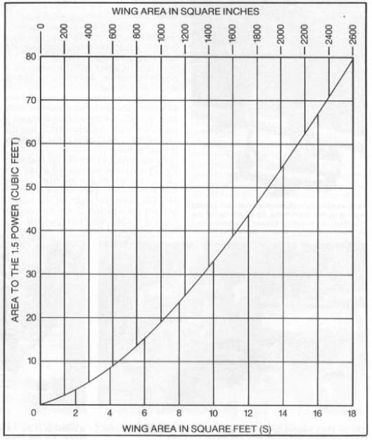
Figure 1 I said earlier that the WCL of a scale model of scale weight will be the same as that of its full-scale prototype. That is true, but most actual scale models have wing cube loadings on the order of a third lower than their prototypes, because we commonly build our scale models lighter than scale weight. The reason is that we wouldn't like the way scale-weight models fly. They would have to fly a bit fast for our human reflexes, especially old reflexes like mine. If scale event rules required scale weight as well as scale dimensions, the flight part of the event would suffer greatly. So model WCLs are a little lower than full scale WCLs, but model wing loadings are many times lower than full scale WLs. True or mathematically correct velocity scaling requires that the model fly at the prototype speed divided by the square root of the scale factor. Quarter-scale models should therefore theoretically fly half as fast as their prototypes, and one sixth scale models should fly 41% as fast. However, I understand that scale judges sometimes grade down a scale model whose flight is too fast to "look scale." Actually, as we usually build lighter than scale weight, most of these scale models are able to fly at a lower scale speed than their prototypes, but "apparent" scale speed differs from true scale speed.
A year ago I mentioned that others had also proposed similar solutions to the wing loading problem. Only when the letters came in after my cube-loading column was published did I realize how many others, and how long this effort has been going on. Others have called it cube loading, wing volume loading, density factor, flyability factor, volumetric loading, etc. Some of the proposals were identical to what I am now preaching, but they sometimes used different names and different units. To give credit where credit is due, these are the people I know of who have been significantly involved. Bob and Roland Boucher, Chuck Cunningham, John McMasters, Ted Off, Dave Platt, Larry Renger, Ken Runestrand, Tom Stark, Ron St. Jean, Joe Wagner, Kent
Walters, R.H. Warring (in England), and Nelson Whitman.
Important Note: December 2021 - Larry Renger uses span, in inches, times the wing area, in square inches, as the multiplier to create a cubic volume in his article "3D Wing Loadings" in the December 1997 issue of Model Airplane News. KM Modelers have a mess with regard to units, even before we talk about cube loading. We measure in inches and feet while the rest of the world uses centimeters. We talk about square inches of wing area until we calculate wing loading, then we change to square feet. Most modelers seem to weigh their models in ounces. I weigh mine in grams on a metric balance and convert the grams to pounds, which is the unit I think in. Then I have to convert the pounds to ounces to calculate wing loading in the usual units. Many different units are possible for our cube, volumetric or density loading parameter. After much thought, I have decided to use ounces and feet in calculating WCL, as these are the units commonly used for wing loading, and the answers come out as small easy-to-remember numbers. In the mid 1970s, Nelson Whitman compiled a list of the WCLs on over eighty published models. I can't publish Nelson's list but I can summarize it, with some shifts to account for changes in design in 14 years. The WCL for gliders will average around 4, R/C Trainers around 6, Sport Aerobatic ships about 9, Pattern jobs about 11, R/C Racers around 12, Scale Models from 10 to 15, and Full-scale Airplanes 15 to 20. I put "average" in italics above because you will find a great range of WCLs for all types of models. WCL will depend on the design, the materials, and the builder, but not the size. I didn't include the range of numbers that Nelson arrived at from his data, because they are too variable, and there will always be some unusual airplanes outside the normal range. The question, "What is normal?" applies. Our goal, for any model, should be the lowest possible weight consistent with adequate power, strength and stiffness. If you have forgotten the thirteen reasons why light models are better than heavy models reread MD&TS for October 1988. You say you like to fly fast and hot, so you want a heavy model. Wrong thinking. A model may fly fast in spite of being heavy, if it has lots of power. If you lighten it, it will fly still faster (because there will be less induced drag); and it can also fly slower. Reducing the weight of a model reduces both its wing loading and its power loading, so there is a double-barreled gain.
Not only do we need to build our models light, but we must build in enough power to fly them the way we want them to fly. Power loading or displacement loading figures help us in deciding how much power we need, or why an existing plane flies the way it does. Displacement Loading (DL) is the weight of the airplane (this time in pounds, to keep the numbers nice) divided by the displacement of the engine in cubic inches. For reasons we discussed a year ago, we can equate our various types of power plants to each other and to full scale as follows: Power loading in pounds per horsepower will be roughly twice our displacement loadings. In other words, our modern two-stroke glow engines average about two horsepower per cubic inch of displacement. The disp. loading or DL of models powered by Schnuerle-ported glow engines and Davis Diesel conversions are simply pounds divided by cubic inches. For older non-Schnuerle glow engines multiply the disp. loading by 1.25. For Quadra-type gasoline engines and for four-stroke glow engines, multiply by 1.5. For antique Diesel engines, multiply by 1.75, and for antique spark ignition model engines, multiply by 2.0. Those of you with engines specified in cubic centimeters can convert the displacement to cu. in. by dividing by 16.4. I received a lot of good help from Roland Boucher, Mitch Poling, and Nelson Whitman on getting power-loading information for electric-powered models. Electric power seems simple compared to internal combustion, but it is not. For one thing, we can get a huge range of power out of any particular electric motor and prop combination by supplying it with a range of voltages (using batteries with different numbers of cells).
If you have an ammeter and a voltmeter, you can measure the input watts to the motor while it is driving the prop (watts = amps X volts). Multiply watts by a motor efficiency of 70 or 75% and divide by 746 to again get approximate output horsepower. This approach will be more accurate than the equivalent-displacement designations given to many model electric motors, because the latter can be valid for only one specific battery and prop.
Rubber-powered models may be compared by relationships proposed to me by reader Barney Frommer. He points out that the potential energy of a rubber motor is proportional to the volume of rubber used. That volume, of course, equals the length of the motor times its cross-sectional area. Barney notes that the duration of the motor run is determined by the length, and the power is determined by the cross section of the rubber (and the prop). Unfortunately, cross sectional area is a square term, and we need a cube term for our power relationship. Otherwise the power loading numbers would vary with scale, as wing loading does. Barney proposes we do what we did to convert wing area to a cube for wing cube loading; multiply the rubber cross section by its square root. Beautiful! Now power loading for rubber powered equals weight of the model divided by the cross sectional area of the rubber motor to the 1.5 power. The units of Rubber Cube Loading are pounds per cubic inch, the same as for displacement loading. Quite by chance the numbers for RCL come out close to DL numbers, but a little lower. For a rough conversion from RCL to DL, multiply the RCL by 1.17. Thanks for the good work, Barney.
How do you want it to fly? For a scale model of an early antique design, to fly only like the original did, you can use the same high power loading or displacement loading the prototype had, which may be a DL of 25 pounds per cubic inch or more. Make sure this is what you really want, though. It will climb very little, may have trouble making moderate level turns without snap rolling, and may descend if you use anything but full throttle. As with WCL, the displacement loading or power loading of a scale model will usually be somewhat lower than the DL or PL of its prototype, again because we like more performance than we would get from a model with scale power, and we lose some efficiency due to the low Reynolds numbers of models.
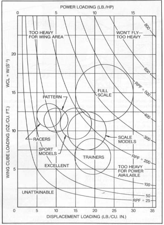
Wing cube loading and displacement loading figures each tell us something about a model, but taken together, they give us a more complete picture of a model's potential. For instance, an airplane with a high wing cube loading may still be a very good racing plane, if it has a very low power loading. Likewise, a plane with a high power or displacement loading but a low wing cube loading may still be a fine special-purpose machine such as a scale Jenny or a motor assisted sailplane.
If we multiply a very low WCL of six by a very low DL of six, we get a very high- performance model (if it will stay together), with an RPF of only thirty-six. Probably this is too light to be practical. At the other end of the range, a heavy underpowered plane with a WCL of fifteen and a DL of twenty would have an RPF of three hundred. It won't be much of a flier, if it flies.
When we learn by experience, we never get out of school.
 |