Where Should You Fly This is linked to an article on the Electric Flyers Only Web site. The article is titled "Advice for Getting Into Flying Radio Controlled (RC) Airplanes". The article will open in a new tab. Close the tab to return here.
Having a Successful First Flight This is linked to an article on the Electric Flyers Only Web site. The article is titled "Advice for Getting Into Flying Radio Controlled (RC) Airplanes". The article will open in a new tab. Close the tab to return here.
Josh Bixler, the creator of FLITE TEST (FT) [www.flitetest.com] has championed a different slant to our hobby. The FLITE TEST Web site promotes the use of simply designed airframes that use inexpensive power systems. The airframes are mostly constructed of Dollar Tree foam board (DTFB) using hot melt glue as the major adhesive for the airframe.
The white foam board, sold by Dollar Tree stores, is known as Readi-Board. It is produced by R.L. Adams Plastic, Inc. and manufactured in Wyoming, MI, USA.
FLITE TEST also uses a brown 'paper' covered version of this foam board to create its laser cut kits. The brown 'paper' covered version is said to be water resistance and the brown paper covering is said to stick to the foam better than the white.
The brown 'paper' covered version, used in their laser cut kits, is available in their store. [store.flitetest.com/] The kits are relatively inexpensive. The FLITE TEST store also carries everything needed to get the airframes flying; recommended power systems, wheels and other accessories, building supplies, tools, radios, battery chargers, batteries, etc. It is truly a one stop shop.
All of their designs have free, downloadable, plans available with step by step how to videos. The amount of time and energy expended to create, test, video and edit the video of all of their designs is unimaginable. The RC community, and especially those being introduced to RC planes for the first time, owe Josh a huge THANK YOU.
The wing for the RUA 2-4-10 is somewhat based on the wing design of FLITE TEST's much smaller Simple Cub.
To get a good idea of how the wing for the RUA 2-4-10 is constructed, watch the 16 minute segment of the video for the wing construction of the Simple Cub.
The major differences between the wing builds is that the wing on the RUA 2-4-10 needs to be laid out and cut out by the builder on DTFB. Instead of using a hot glue gun, the adhesives used are Titebond Original Wood Glue or, alternately, Aleene's ORITINAL TACKY GLUE and Devcon 5-Minute epoxy.
Another Trainer?!?
As an RC flight instructor, I'm always looking for a good trainer to initiate flight instruction. While I've found several commercially available trainers useful for that purpose, I was disappointed with my flight instruction. I was not getting my student pilots to the point I had hoped to reach before the weather became too poor to continue flight instruction.
I decided to 'design' a trainer, that I believed, would be able to introduce and get my student pilots to the solo point faster.
While some of the FLITE TEST designs could be considered capable of this, I wanted something a bit larger for training at our club flying field.
As with all designs, it went through many iterations and evolved through flight testing.
It was designed with a long tail moment, like those found on the FlyZone Sensei and Leisure Amptique. The long tail moment dampens the effect of the elevator. The simple box fuselage, with a shoulder wing placement, is similar to many "stik/stick" planes, but with no real "inner" structure. The horizontal stabilizer/elevator assembly and vertical stabilizer/rudder assembly are joined and "slide" into the back of the fuselage making alignment easy. There is a lot of dihedral built into the wing, which allows for simple, and stable, 3-channel, rudder, elevator and throttle, control. Only requiring 3 channels, or functions, allows the use of the simplest of radio control systems. The power system was selected so that either a 4S A123 1100mAh LiFePO4 pack or 3S 165g to 200g LiPo pack could be used without changing the ready to fly (RTF) weight or center of gravity (CG). The light wing loading, about 7.7 ounces per square foot, and light wing cube loading factor of 3.8, allow the plane to be forgiving in the air and relatively easy to line up to land. It will land on its own, once lined up on the flying field. The light loading also allows the power system to 'sip' capacity (mAh) out of the battery. It handles fairly moderate breezes well. Its almost 60" wingspan makes orientation quite easy, even if it is left all white. It can be flown a lot closer to the pilot than other trainers of this size. It flies slower than most "commercial" trainers.
Why Two Airframes?
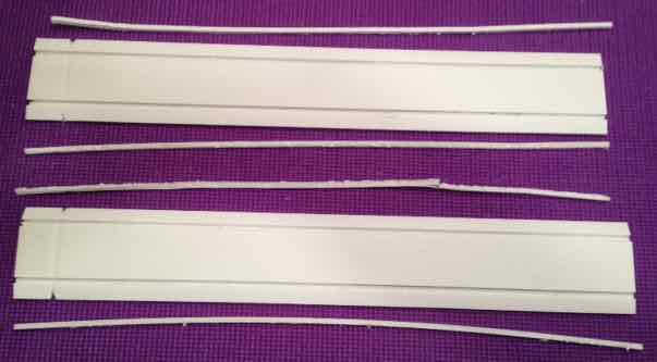
Four pieces of Dollar Tree foam board (DTFB) are required for each airframe for a total of eight pieces.
The underlying concept for this plane, with two complete airframes, is based on "The Power of Two".
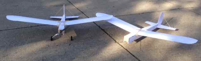
The Plane
No matter how you look at the plane, it is not pretty! In fact, it quite ugly, hence the name Really Ugly Airplane, RUA. Instead of the typical build of one airframe for most designs, two complete airframes are constructed. The parts for the two completed airframes cost about $10, hence 2-4-10 or two for ten dollars.
Both airframes can be completed in about 8 hours of actual building time. The second one goes together even more quickly than the first. A few templates and other tool-like parts are made during the construction of the number "One", and they are reused when making number "Two". Number "Two" is also quicker to build because the procedure is fresh in the builder's mind.
Specifications
Type: Scratch-built, Park Flyer, Trainer
Skill Level: Beginner builder & Beginner flier
Construction: Adams Readi-Board foam board or, alternately, Ross foam board, plywood, piano/music wire, wooden dowel rod and a few commercially available parts
Plan Form Wing Span: 58-1/2" (verified by measuring wing 7 of my build)
Wing Chord: 10-3/8"
Plan Form Wing Area: 583.8 sq.in. verified (about 4 sq.ft.)
Length: 45"
RTF weight: 30.9 oz. or 1.9 lb. (DTFB prototype version)
Area wing loading: 7.6 oz./sq.ft.
Wing cube loading factor: 3.8
Flight Duration: At least 15 minutes using a 3S 2100mAh LiPo battery
Typical Maximum Watts in per pound: 90 (way, way more than ever will be necessary)
Approximate Maximum Pitch Speed at 7500 RPM: 39 mph
Approximate Stall Speed: 5.3 mph
Prototype wing weight: 247g/8.7 oz.
Prototype completed fuselage weight, no battery: 449.3g/15.8 oz.
Maiden Flight Date: October 29, 2017
Radio System Recommended Transmitter: 2.4GHz 3-channel and up, i.e. Tower Hobbies 424 with receiver Transmitter used: Tactic TTX650 (discontinued), today's equivalent is a Tactic TTX660 Also being used and tested is a FlySky i6X transmitter with FlySky iA6B receiver
Recommended Receiver: 3-channel and up to match the transmitter's brand
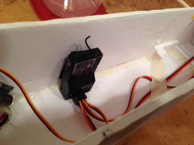
Receivers Used: Tactic TR624 6-channel, Tactic TR625 6-channel, and with the FlySky transmitter FlySky iA6B Recommended Servos: two "9g" servos, they are about 1" long, 1/2" wide and 1" high
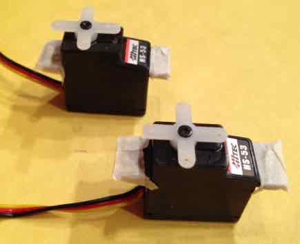
Servos Used: Two Hitec HS-53, 0.9" long, 0.48" wide, 1.07" high, weight - 9.0g, Two Tactic TSX5 were also tried and NOT recommended
Recommended Servo Extensions: Two 16" to 18"
Servo Extensions Used: Two Hyperion Extension Cable - JR Twisted 450mm
Four different adhesives are used in the construction of the airframes.
Glues
Titebond Original Wood Glue was used for much of the construction of the first 8 prototypes. It is widely available. It dries quickly when spread out into a thin layer for laminating parts. Titebond can be wiped off with a finger to provide a thin layer on surfaces to be laminated. The excess glue can be wiped from a finger onto a rag. Nothing more is required to 'clean' the finger of glue.
An Alternate Glue A ninth airframe was constructed using Aleene's ORIGINAL TACKY GLUE, purchased at Walmart and found in craft departments of many stores. It worked equally as well as Titebond and maybe dries a little faster. It also dries clear.
Long 'runs' of either of these glues can be made, as when building the wing, and then the parts can be joined and weighted down until the glue dries.
When the word 'glue' is used during the construction, it means to use either of these glues with straight pins or weights as necessary.
Devcon 5-Minute Epoxy Its useful working time is about five minutes. It takes about an hour to cure.
All epoxy adhesive is a two part mixture. It can be mixed on a 'plastic' container top, like many margarines come in, using a toothpick. It should be mixed throughly.
When the word 'epoxy' is used during the construction, it means to use 5-Minute epoxy. There are no instances during the construction that require an epoxy joint to be pinned, clamped or taped.
Epoxy can be cleaned from the hands and fingers with denatured alcohol and a rag. Hands must be throughly washed after the alcohol is used.
Other brands of 5-Minute epoxy can be used, but I have found Devcon brand to be the best.
Low temperature, craft-type, glue gun and its hot melt glue sticks are used in a few places. It does not need to be a special type. An inexpensive type found at craft stores and other places that sell 'crafting' items works fine.
When the words 'hot glue gun' are used during the construction, it means to run a bead, or place a dab, of hot melt glue, as required.
Elmer's Washable School Glue Stick is used to affix the printed paper templates to the foam board. It is available where 'school supplies' are sold.
Tapes There are three different types of tape used during construction.
Fiberglass Filament Tape, 0.9" x 60 Yards, Other brands of about 1" wide filament tape are acceptable.
In the construction notes, this tape is called out as "strapping tape".
Firewall and Landing Gear Available - US & Canada Only
A note on cutting plywood. The Firewall and Landing Gear Plate are made of 1/4" plywood. Cutting plywood accurately, by hand, is very difficult. I use a Dremel table saw, which is no longer available. A full size table saw, or band saw, could be used.
I acquired a ROCKWELL BladeRunner X2 as a backup for my old Dremel table saw. (The Power of Two) It can be used to cut the 1/4" plywood, although it does cut a very slight angle along the edge of the wood.
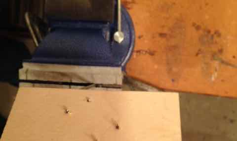
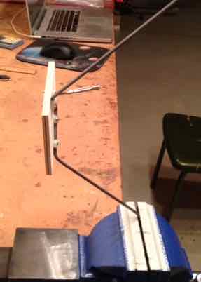
A note on music wire (AKA piano wire)
K&S Precision Metals produces 36" lengths of tempered music wire. It can be found in many hobby shops, if you can find a hobby shop!
K&S music wire can also be found at online RC retailers and Amazon.
Unfortunately, online, it is sold by the 'bundle', not the piece. Only one 1/8" x 36" piece is required for this project.
It is difficult to cut without using a Dremel Rotary tool and cut-off wheel.
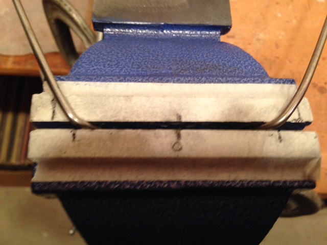
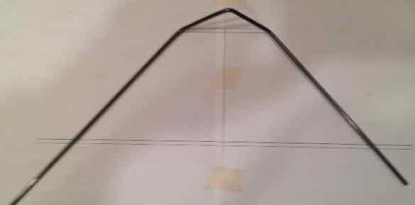
I can supply the pre-bent landing gear wire (1), with flat spots ground on the wire axles for the wheel collar set screws, for the cost of a single piece of wire.
Pre-cut Firewalls (2) and Landing Gear Plates (2) can be provided for the cost a 1/4" x 6" x 12" sheet of plywood.
The shipping will probably cost more than the materials cost, but the wood will be cut and the landing gear wire pre-bent.
You will still have to do the marking, drilling, etc., on the Firewalls and Landing Gear Plates.
If you'd like the Firewalls (2), Landing Gear Plates (2) and 1/8" music wire landing gear (1) for the cost of the materials plus shipping, send an email to me and I will arrange it.
Only if the 1/8" music wire landing gear are to be made by you. Ken can supply finished 1/8" music wire landing gear Small file for metal
hammer
Shopping List for Hardware or big box hardware/lumber stores like Lowes, Home Depot, Menards, etc. Several household items are duplicated on the list.
3/8" chorded, electric hand drill (or equivalent)
Drill bits: 1/16", 5/64", 1/8", 11/64", 5/16"
Small flat tip screwdriver
Larger flat tip screwdriver
Small tip Phillips screwdriver
Medium size tip Phillips screwdriver
3/4" to 1" inch tan masking tape
Single Edge Razor Blades
X-ACTO knife & #11 blades
Titebond Original Wood Glue: Aleen's ORIGINAL TACKY GLUE may be substituted - listed later
Devcon 5-Minute Epoxy
Packaging tape such as Scotch 1.88 in. x 65.6 yds. Shipping Packaging Tape 'L' Square/Carpenter Square: 16 in. x 24 in. Steel Framing Square Aluminum Straight Edge Ruler 48 in. Aluminum Straight Edge Ruler Medium grit sandpaper
Hot melt glue gun and glue sticks for it (low temp, cheap is fine)
6" Diagonal Cutter: (wire cutter)
Crescent wrench: (smallish)
Needle Nose Pliers
1.5mm Hex key tool: (unfortunately, usually only found in metric sets of hex key tools)
60" Building Surface: Workbench, See A Word About the Building Surface Credit Card (expired): old credit card or old plastic gift card
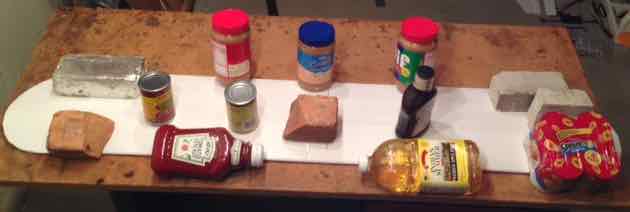
Bricks: similar to this in size, really handy, also just handy to have around the house too
Safety glasses
Only if the 1/8" music wire landing gear are to be made by you. Ken can supply finished 1/8" music wire landing gear Hammer
Dremel 200 Series Rotary Tool
Dremel cut-off wheel
Dremel grinding stone/wheel
Bench Vice: 4" or larger similar to this
Only if the 1/4" Firewall & Landing Gear Plate are to be made by you. Ken can supply the 1/4" plywood Firewalls (2) and Landing Gear Plates (2) An electric saw to cut 1/4" plywood cleanly with square corners and sides.
Shopping list for multi-merchandise stores; i.e. Walmart, Meijer, etc. Just about anything missing from the household list as well as some of the tools and supplies found in the Hardware Store shopping list.
And:
Aleene's ORIGINAL TACKY GLUE (a substitute for Titebond)
Ross foam board: Walmart only, substitute for Adams Readi-Board from the Dollar Tree Store (Qty. 8)
1/8" wooden dowel (Qty. 2)
3/16" wooden dowel (Qty. 1)
Elmer's Washable School Glue Stick
Craft Sticks
#64 rubber bands
ACTIVE Yoga Mat: 5mm at Meijer: See A Word About the Building Surface
One somewhat harder to locate tape: 0.9" wide filament tape.
It can be found at Staples and maybe other office supply stores. It is extremely strong and doesn't tear like other "packaging tapes".
Dollar Tree Foam Board: Adam's Readi-Board: Dollar Tree stores (Qty. 8), Ross foam board from Walmart may be substituted
Items from Tower Hobbies if the 1/4" Firewall & Landing Gear Plate and 1/8" landing gear wire are to be made by you. Tower Hobbies Plywood 1/4 x 6 x 12" K&S Music Wire 1/8" 36" (9) Remember that Ken can supply the 1/4" plywood Firewalls (2) and Landing Gear Plates (2) and pre-bent and filed landing gear (1)
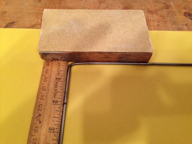
Almost any size flat, unbowed, block of wood, that fits the hand well and has square edges, can be used.
For this project, I made a new sanding block out of an ArtMinds Small Wood Plaque, 5.1" x 3" x 0.78" from Michaels. It is not a solid block of wood, but it will work. The edges are not true to the bottom of the plaque, where the sandpaper is applied, but the short side edges are close enough to 90 degrees to be used for truing. The short sides are not bowed.
I marked 150 grit sandpaper where the 'block' would be applied. A small amount of glue was spread on the back of the sandpaper, in the marked area, and wiped to a very thin coat with a finger. The excess was wiped on a rag.
The glue was applied in the same manner to the outside bottom of the plaque. The 'block' was placed onto the glued area of the sandpaper. A weight was placed on the 'block' with the sandpaper under it. It was weighted for several hours and then the remainder of the sandpaper sheet was cut off around the block with a single edge razor blade. It was then ready for use.
The edge of the sanding block can also used as a 'squaring' or truing device.
The Building Surface A 60" (5'), or greater length, hard, flat building surface is required. There are no pins, or anything, to stick into the surface, but a razor blade will be used to cut through the foam board on the building surface.
A Workbench I've been fortunate to have a workbench with a 2' deep x 5' wide top for more than 45 years. It sets 33-5/8"" from the floor to the work surface. (I do wish it was higher.) It has a metal frame with two drawers and the top work surface is 1" thick. It is 'bear' to move, and I've moved three times since I've had it.
If you are a DIY person, you can build one. I suggest something like the ones in these two videos.
This video shows a 2' x 4', but as a DIY it is easy to extend to 5' wide.
This video shows another technique, and the finished table is larger than needed. The technique can be adjusted to a 2' x 5' top, if desired.
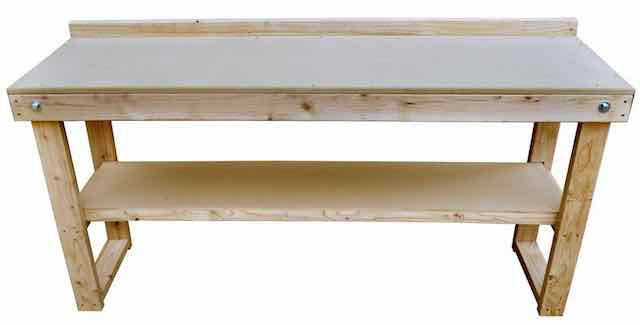
72 in. Fold-Out Wood Workbench @ Home Depot
If you are not a DIY type person, I'd recommend this one from Home Depot for about $80. It is a kit that has to be assembled, but it should be much easier to move compared to mine. It can also be set up, taken dawn and stored at will.
If you don't want to mar the top of your new work bench, a 5mm Yoga/fitness mat can be spread out on the top of the work surface.
I picked up an ACTIVE Yoga Mat, Purple, 5mm at Meijer for less than $15 including tax. It worked well on my bench when cutting out the foam board parts. It has an antiskid surface too.
To be able to continue the building sequence uninterrupted, two more 60" flat surface areas, to set partial constructions on while the glue is curing or drying, are recommended. The alternate surfaces are covered with wax paper, when necessary, to prevent any adhesive from getting onto them.
Lithium Polymer (LiPo) Batteries come from different suppliers with the supplier's choice of power lead connector. There is no standard. Different types, or styles, of connectors are not compatible with each other.
A mating power connector needs to be added to the power leads of the electronic speed control (ESC) to mate with the power connector on the battery. In this case it would be a male XT-60.
The appropriate connector is soldered onto the wires of the ESC and the solder joints covered with heat shrink tube.
Soldering the leads to the ESC requires at least a 40W soldering iron, not gun, leaded 60/40 rosin core solder and some heat shrink tube in the appropriate diameter for the wire. It also requires the 'skill' to solder well.
The February, 2018 Ampeer has an article called, "Soldering for RCers" by Gary Gullikson. As the title implies, it covers how to solder.
I HIGHLY RECOMMEND replacing the XT60 connectors on the batteries with Anderson Power Pole (APP) connectors.
APP connectors are crimped, not soldered. No soldering skills are required. No shrink tube is necessary, as the crimped wire and connector joints are inside the housing for the connector.
A crimper for the APP connectors and a dozen pairs of connectors can be purchased from West Mountain Radio (see the online Power System parts list) for a lower price than a decent 40W soldering iron, a roll of leaded 60/40 solder, appropriate diameter heat shrink tubing and a pair of male XT60 connectors.
The type of APP connectors that we use in RC all fit in the same housing. There are three different sizes of contacts. The numbers associated with the size are nominal, not cardinal numbers. Their names are; 15A, 30A and 45A. 15A does not mean that it will handle only up to 15 amps. It means that it is the smallest connector. 45A does not mean that it will handle only up to 45 amps. It means that it is the largest size to fit in this type of housing.
The amount of amps the contacts can handle is the same as the largest size wire gauge (AWG) it can accommodate in the wire receiver of the contact.
Remember the numbers for the contacts are nominal, not cardinal.
15A up to 16 AWG
30A up to 12 AWG
45A up to 10 AWG
A YouTube video titled "Installing 45A Anderson Powerpole connectors for RC applications" demonstrates how to install APPs on a battery. The procedure is exactly the same for the 15A and 30A contacts.
IT IS EXTREMELY IMPORTANT TO NOTE THAT THE AUTHOR OF THE VIDEO ONLY SNIPS ONE POWER LEAD AT A TIME ON THE BATTERY HE'S WORKING ON. HE COMPLETES ONE LEAD BY CRIMPING ON THE APP CONNECTOR AND INSTALLING ITS HOUSING BEFORE SNIPPING THE OTHER LEAD AND REPEATING THE PROCESS. This is how it should be done!
The power leads are cut, one at a time, using a 6" Diagonal Cutter (wire cutter). A wire stripper is shown in the video stripping the wire leads. A single edge razor blade can be used instead of a wire stripper. The blade can be held somewhat stationary with a bit of pressure on it while pressing on the wire and the wire 'rolled' on a kitchen type cutting board to cut the silicone covering.
For polarity protection, the housings have a 'slot' on one side of the housing and a ridge on the other. The positive and negative housings can be joined together to create a polarity protected connector.
Selecting a Radio System is a difficult decision for a person new to RC airplanes. Ready to fly (RTF) packages include an installed onboard radio system including the receiver, electronic speed control (ESC) and servos as well as the handheld radio transmitter for controlling the airplane. When completing a scratch built model, it is just one more decision to make.
Today's 2.4GHz radio systems, provided by US suppliers, Horizon Hobby (Spektrum, Futaba, Hitec, Tactic, and Tower Hobbies) and Aloft Hobbies (FrSky), are all pretty reliable.
It is important to keep in mind that while all of the transmitters are transmitting across the 2.4GHz band, using spread spectrum frequency hopping, the way that they communicate with their 'receiver', their protocol, is different for each brand. A transmitter of one brand cannot usually communicate with another brand's 'receiver'. The user is then somewhat 'locked into' that brand.
Many, if not most, of the modelers, who've been in the hobby for awhile, will have more than one transmitter and may even have different brands of transmitters for different purposes.
This project only requires the simplest of radio systems.
Only three functions are required; roll is combined with yaw, due to the aircraft's design, and pitch (on the right stick) and throttle (on the left stick).
The following information applies only to my recommended radio system. If you already have a transmitter with a matching receiver, please read "Using Your Own Choice of Radio System".
I have suggested, and recommend, a Tower Hobbies' brand radio system. It is relatively inexpensive and comes with its companion receiver. Tower Hobbies, which is now part of Horizon Hobby, was an extremely reputable supplier in the US and backed up what they sold.
IMPORTANT UPDATE - June 2018 Tower Hobbies was purchased by Horizon Hobby earlier this year. Horizon Hobby sells Spektrum brand radios. The Spektrum brand has no inexpensive 4-channel radio system like the Tower Hobbies version. Whether the Tower Hobbies' version remains available is unknown at this time, June 16, 2018. The Tower Hobbies' Web site notes "Late Jun" for deliver. An alternate brand radio system is being tested in an RUA 2-4-10 prototype at this time.
That radio system uses a protocol known as SLT. It is also the same protocol as used by Tactic radio systems. The SLT protocol can also be selected, as one of two protocols, on the newest Hitec radio systems.
When using only 3-channels of a 4-channel (4 function) system, or more, the roll/yaw control needs to be on the right stick for this model with a large amount of dihedral. That means that the rudder servo needs to be plugged into what the supplier calls the 'aileron' channel. On a Tower Hobbies or Tactic radio system that is Channel 1 on the receiver. The receiver channel position will vary with other brands of receivers.
A special note for Tower Hobbies and Tactic radio systems
Channel 3, the throttle channel, on the transmitter needs to be reversed to operate with electronic speed controls (ESCs). This also applies to Futaba systems. Other systems will vary.
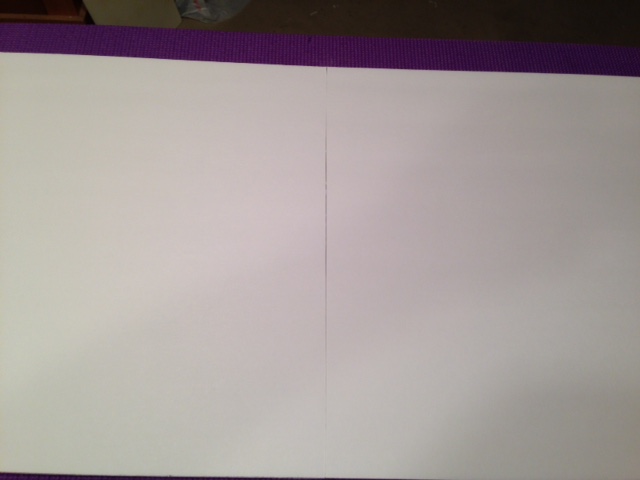
Before printing any of the parts templates, download and print the Printer Test.
DO NOT PRINT FROM THE BROWSER! Download the .pdf files to your computer before printing.
Setting up the free Adobe Acrobat Reader DC to print the .pdf files.
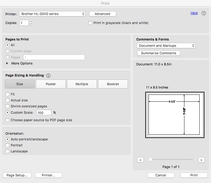
The Print Window in the Adobe Acrobat Reader DC
The screen capture shows how to set up the print screen of the Adobe Acrobat Reader DC before printing.
Printer: your printer name
Copies: 1
Pages to Print - All
Page Sizing and Handling - Select the Size tab (shown as a gray rectangular tab in the screen capture) and then either Actual size or, as shown in the screen capture, Custom Scale: 100%
Orientation: Auto portrait/landscape
Click the Print box
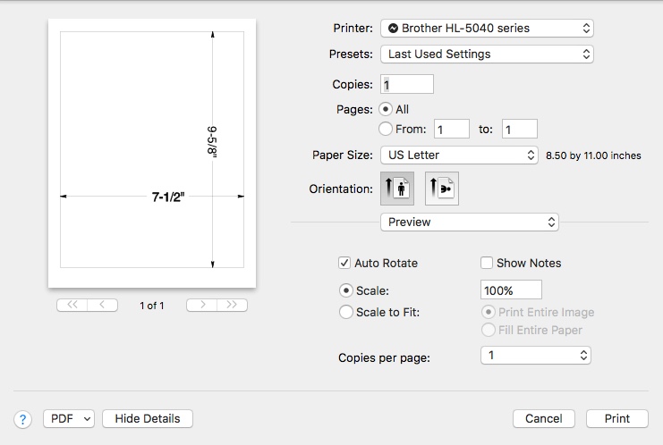
Mac users may also use Preview.
The Print Window in Mac OS Preview
Select your printer and then set up as shown in the print window above.
Click the Print box
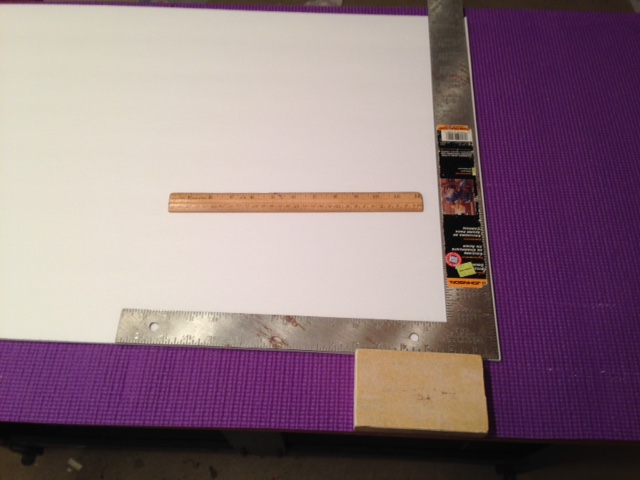
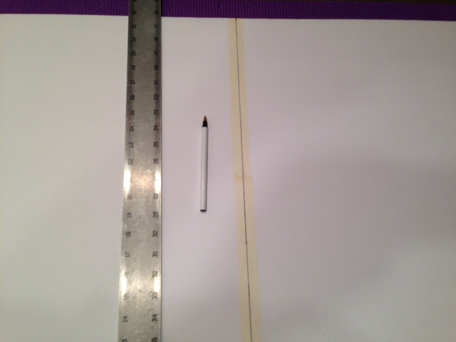
Measuring the Printed Rectangle
Required Items: the printed rectangle, a measuring device like a 12" ruler
Once the rectangle is printed, measure the dimensions. The rectangle should be 7-1/2" wide and 9-5/8" long. The measurements of the printed rectangle should be within 1/32" of the noted dimensions.
If the measured dimensions do not match the printed dimensions, double check to see that the Print Window was set up correctly, and print again.
If the measured dimensions are still way off, as printed on that printer, try another printer.
The idea behind this plane is to assemble two complete airframes.
DO NOT ATTEMPT TO PRINT OUT ALL OF THE THE PARTS TEMPLATE PAGES AT ONE TIME. Print only enough pages to complete the series of pages to be joined.
The pages containing the parts templates have alignment/cut marks printed on them. The alignment/cut mark is a cut mark before joining the printed pages together and an alignment mark when joining the pages with tape. Either short pieces of clear cellophane tape or masking tape can be used to join the pages. Once the pages are aligned and joined with small pieces of tape, fully tape all of the joint lines between the pages.
The individual parts templates are cut from the joined pages. They are NOT cut on the actual parts outline. The parts are cut out of the joined pages approximately 1/4" outside the actual parts border line.
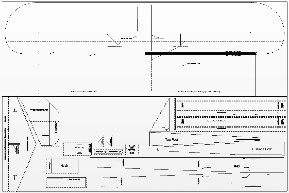
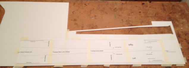
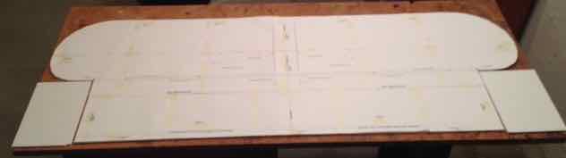
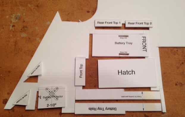
The Parts Layout
The parts layout
There are four absolute positions for the parts layout. The Spar parts are cut from the top, righthand corner of one sheet of DTFB. The Fuselage Floor and Top Rear are cut from the area just below where the Spar Parts were cut. The Horizontal Stabilizer and Elevator (H-Stab) is cut from the lefthand side of another sheet of foam board. The Fuselage sides are cut from the bottom of the two previously used pieces of DTFB, after they have been joined.
All of the other parts are cut out from relative positions typified in the diagram.
Scrolling back and forth to the parts diagram is not necessary. A click on the words/link Parts Layout, anytime that it appears, opens the parts diagram for reference.
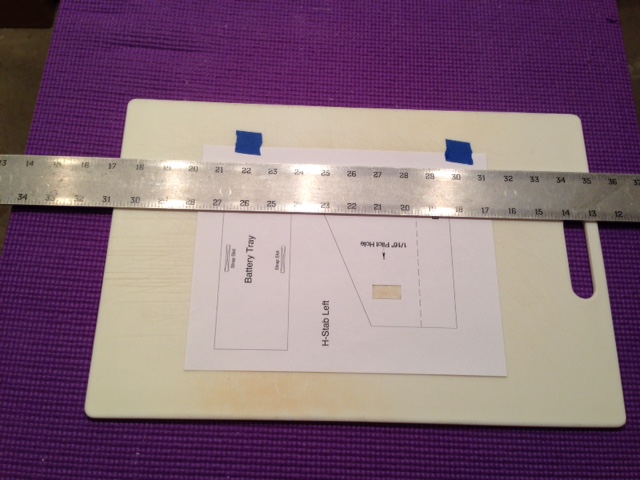
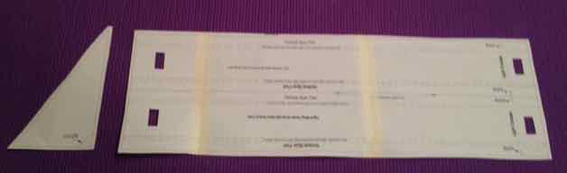
An Example for Creating the Templates and Parts - The H-Stab pages
The completed Horizontal Stabilizer (H-Stab) template also contains the templates for the Battery Tray, Front Rear 1 & 2 Top crosspieces, the oversized Front Top crosspiece and the Hatch.
Save the H-Stab Template to your computer H-Stab.pdf and then print it. From now on, this process is called Save, then print.
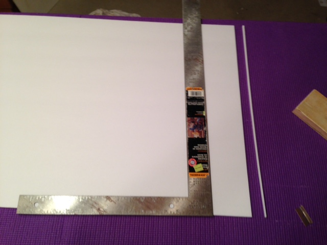
Items Required for joining the pages into a complete template: the printed 8-1/2" by 11" pages of paper to be joined, 48" metal straight edge, single edge razor blade, tape, kitchen-type cutting board
Joining the three pages into a complete template sheet
First, cut out all rectangles for the masking tape on the template page, then, using the alignment/cut marks, cut the right vertical edge off of the H-Stab Left and H-Stab Middle printed pages by aligning the metal straight edge with the vertical cut marks. Run the single edge razor blade completely across the page. Only the masking tape rectangle needs to be cut out on the page named H-Stab Right.
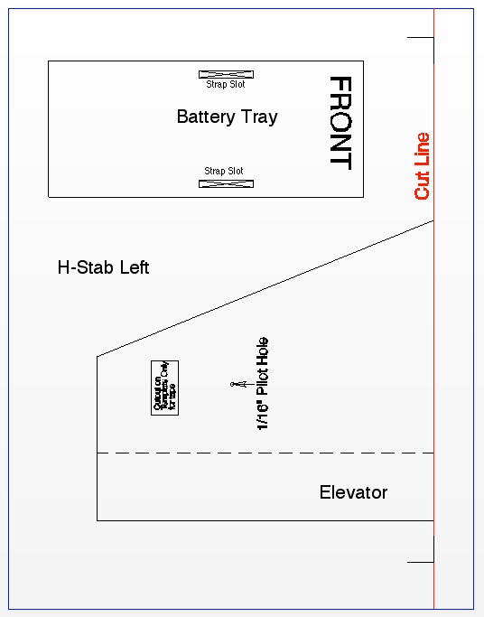
Example H-Stab Left showing the position of the Cut Line in red
The blue lines in the diagram represent the full page of paper. The line used to cut off the right edge of the paper is shown in red.
Besides the template for the name of the group of printed pages, the joined pages may also contain other templates. For example, the H-Stab row of pages also includes the templates for the Battery Tray, Rear Front Top 1 & 2 crosspieces and the Front Top crosspiece with the Hatch.
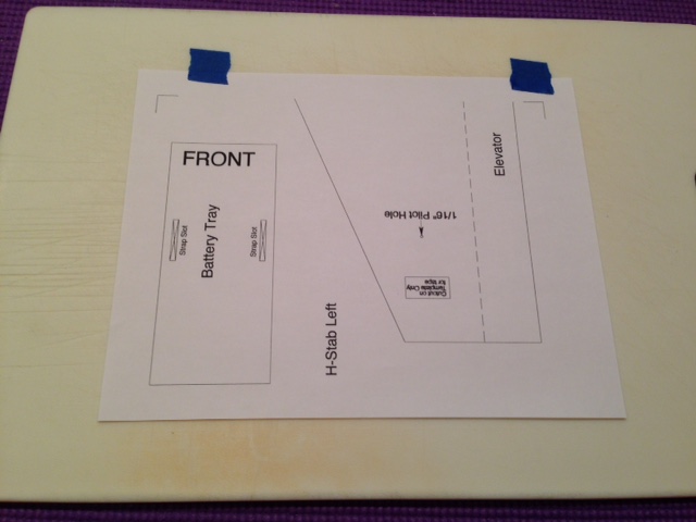
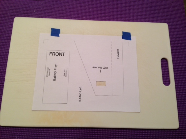
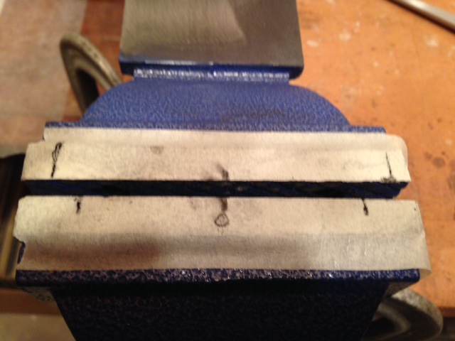
Blue tape used for photographic purposes.
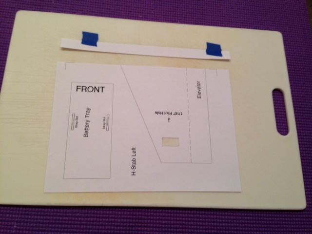
1. Using two small pieces of tape, tape the edge of the paper to be cut off to a cutting board. Note that the rectangle for the masking tape, to hold the template to the foam board, has already been cut out.
2. An Elmer's Washable School Glue Stick is used to hold the templates to the foam board for cutting. Some large templates also have 1" by 1/2" rectangles cut out of them. Tape is placed over the cut out rectangles to help hold the large template to the foam board along with the Elmer's Washable School Glue Stick. Cut out any of these rectangles first. They can be cut freehand using a single edge razor blade.
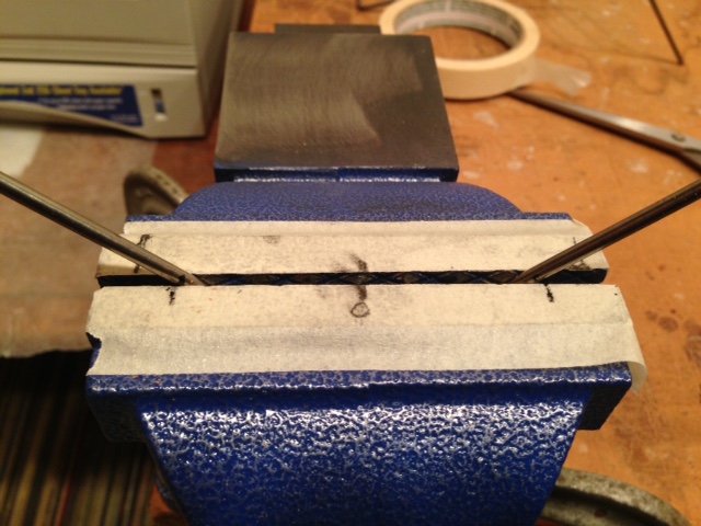
3. Align the metal straight edge using the Cut Lines.
4. Cut all the way across the paper using a single edge razor blade drawn along the straight edge.
5. Remove the template page, and scrap of paper with the tape on it, from the cutting board.
6. Repeat the process for H-Stab Middle.
7. Cut out the 1" by 1/2" rectangle on the page noted as H-Stab Right. No edge trimming is necessary on H-Stab Right.
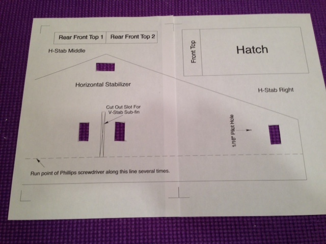
Taping the pages together
1. On a flat surface, align the right, cutoff side of H-Stab Middle over the left side of H-Stab Right. The two pages are aligned using the printed alignment/cut off lines and lines on any overlapping template part as a guide.
2. Once the printed lines are in good alignment, place a couple of small pieces of tape between the two pages.
3. Repeat the process to attach H-Stab Left to H-Stab Middle.
4. Completely tape the joints between the pages over the H-Stab template.
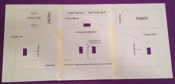
Cut out the templates
1. Cut all of the parts' templates out of the joined pages leaving about a 1/4" border around each part template.
2. Set all of the templates aside except for the H-Stab.
Creating the Horizontal Stabilizer Part
Required Items: the H-Stab template, a new piece of DTFB with the sticker removed, single edge razor blade, X-ACTO knife w/#11 blade, 48" straight edge, Elmer's Washable School Glue Stick, masking tape, 1/16" drill bit, sanding block, strapping tape, scissors, 1/4" diameter shank Phillips screwdriver, 12" ruler
1. The H-Stab part is quite large. Use an Elmer's Washable School Glue Stick and masking tape over the cut out rectangles to hold the template to the foam board.
2. The H-Stab aligns vertically on the left side of the foam board as shown on the Parts Layout.
3. Flip the template over and run an Elmer's Washable School Glue Stick around the edges and across the middle of the template.
4. Flip the template back over. Align it on the foam board as shown on the Parts Layout and press it down around the edges.
5. Apply masking tape over the Cutouts.
6. Cut out and remove the slot for the Vertical Stabilizer sub-fin using the X-ACTO knife and single edge razor blade. The X-ACTO knife works best for the short sides of the slot.
7. Use a 1/16" drill bit to hand drill the two pilot holes shown on the template.
8. Use a 1/4" shank Phillips screwdriver to crease the line between the Horizontal Stabilizer and the Elevator. Set the straight edge off the line between the Horizontal Stabilizer and Elevator so that the "pointy" tip of the Phillips screwdriver can be pressed and pulled across the line creating a crease. The creasing should be very "heavy" and almost through to the paper on the other side of the foam. This process creates the hinge between the Horizontal Stabilizer and the Elevator.
9. Cut out the outline of the H-Stab part.
10. Remove the remainder of the foam board piece and set it aside.
11. Remove the template paper from the H-Stab and throw it away.
12. Lay the hinge line over the edge of the building surface and "crack open" the Hinge Line by holding the Horizontal Stabilizer part of the H-Stab and pressing down on the Elevator.
Note: The single edge razor blade can be pulled part way through the foam board along the hinge line made with the Phillips screwdriver to 'encourage' it to crack open.
13. Turn the H-Stab assembly over on the building board.
14. Fold the Elevator over the top of the Horizontal Stabilizer.
15. Set the hinge line near the edge of the building surface.
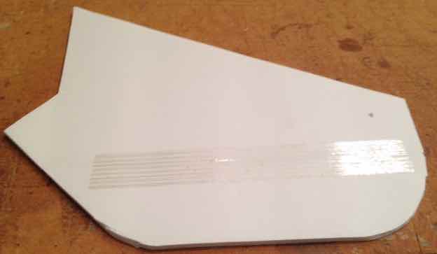
16. Use a sanding block, moved in both a horizontal and a circular motion, to bevel the surfaces of the Hinge Line so that the Elevator moves freely in both directions. This requires flipping the H-Stab over to do the "other" hinge surface.
17. Set the H-Stab on the building surface with the sanded surfaces of the Hinge Line on the building surface.
18. Place two 9" long pieces of strapping tape, NOT packaging tape, over each side of the Hinge Line. Attach the tape starting about 1/2" from each end and run it toward the center.
19. Flip the H-Stab back over so that the taped hinge side is on the building surface. Hold the H-Stab flat. 'Lift' the elevator to its full extent. Check to see that the elevator's trailing edge can move at least 7/16" vertically. Sand the hinge angle as necessary to achieve the movement of the elevator. A 12" ruler is a bit handier for checking this movement, compared to the 48" metal straight edge. (Note: this will really be the 'down' movement of the elevator.)
20. Set the H-Stab aside.
In all of the following, "Cut out the template." means to cut out the part template with about a 1/4" border. "Cut out the part outline." means to cut the solid lines that define the actual part outline. Some solid lines DO NOT define the parts outline. DO NOT cut those lines. Cut only the solid lines that define the actual part outline when it is affixed to the foam board.
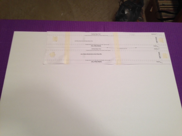
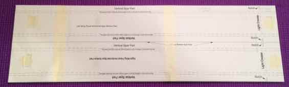
Required Items: the 3 printed Spar template pages, 48" straight edge, kitchen type cutting board, single edge razor blade, masking tape (or clear cellophane tape, i.e. Scotch tape)
The Spar template pages are assembled in exactly the same way as the H-Stab template pages.
Building the Spars
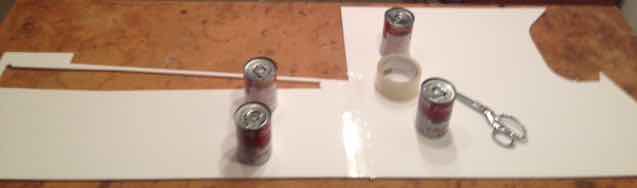
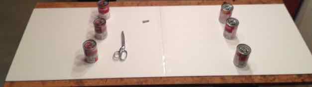
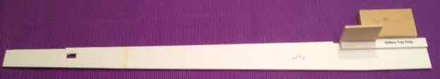
Required Items: the joined Spar template pages, one piece of DTFB with the sticker removed, single edge razor blade, X-ACTO knife w/#11 blade, 48" straight edge, metal 'L' square, sanding block, 3/16" shank Phillips screwdriver (this is a little smaller than the one used to create hinge on the H-Stab), glue, Elmer's Washable School Glue Stick, straight pins, masking tape, weights (full cans or bottles of "stuff" found in the pantry will work), wax paper, rag, old credit card or plastic gift card
The Spar row of pages contains the template for the spar parts and a 90-degree triangle template.
Note: Two more tape cut outs have been added to the Spar parts since the photo was taken.
1. Cut out the triangle template with about a 1/4" border surrounding it. Set it aside with the templates cut from the H-Stab pages.
2. Cut out the Spar parts template with about a 1/4" border around the whole Spar parts section.
3. Place the new piece of DTFB on the cutting surface with the 30" width of the foam board running the width of the cutting surface.
4. Check for the spar position on the DTFB sheet on the Parts Layout.
5. Run an Elmer's Washable School Glue Stick on all four edges of the backside of the Spar parts template and place an X of glue corner to corner.
6. Flip the template over and position the template in the top, right corner of the DTFB as shown in photo. Once in position, smooth out and press down the template to affix it to the foam board.
7. Place masking tape over the 6 cutouts to help hold the template in place.
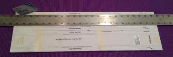
8. Before doing any cutting, align the 48" straight edge on the Spar parts template so that it is "just off" the long dashed lines on the two Horizontal Spar Bottom Parts enough to allow the point of the 3/16" shank Phillips screwdriver to be drawn along the long dashed lines to create creases on the Horizontal Bottom Spar Parts.
Only enough pressure is used to lightly crease these lines on both of the Horizontal Bottom Spar Parts. The creases encourage the Horizontal Spar Bottom Part to bend there when dihedral is added to the wing. Make the creases on the Horizontal Spar Bottom Parts with the point of the Phillips screwdriver. The Vertical Spar parts do not need creasing.
9. Use an X-ACTO knife with a #11 blade to cut out the notches in the spar verticals.
10. Use a single edge razor blade and 48" metal rule to cut out the large rectangle that contains the two spar parts.
The dashed lines on the template are to only be partially cut through the foam, leaving the paper on the bottom of the foam board intact. Using a single edge razor blade, cut through the dashed line about 1/2 way through the foam. Run an old credit card or plastic gift card through the cut to extend the cut down but not break the surface of the paper on the bottom of the foam board.
When cutting the lines for the channels, it is best work from the outside of the template on both long edges towards the middle. Sometimes, when making these cuts, the paper template may pull away from the foam board.
If you accidentally slice through the bottom paper in some places, just tape it back together.
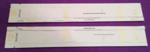
11. Cut the channels into each of the spar parts.
12. Cut the two spar parts apart on the center line between them and remove the paper template from the parts.
13. Remove the top paper with the foam attached from the channel by pulling it out and leaving the bottom paper in place on the building surface.
14. Set the Spar Parts aside.
Cut out the 90 degree Triangle
1. Check for the 90 degree triangle position on the DTFB sheet on the Parts Layout. It is to the left of where the Spar parts were cut out.
2. Return that DTFB sheet to the cutting surface.
3. Use an Elmer's Washable School Glue Stick to affix the template to the DTFB and cut it out. Don't forget to cut the corner off at where the triangle has its 90 degree angle.
4. Set the large piece of DTFB aside and remove the the paper template from the triangle.
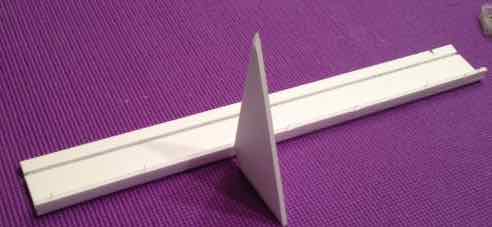
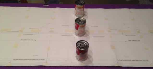
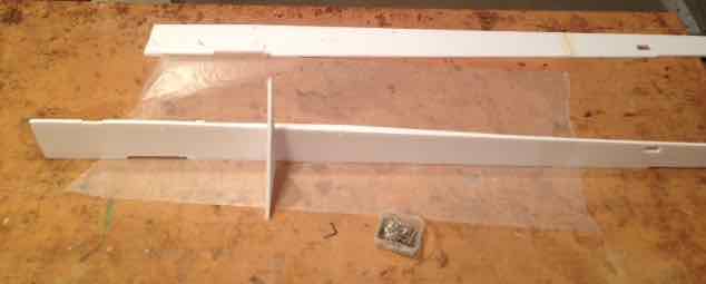
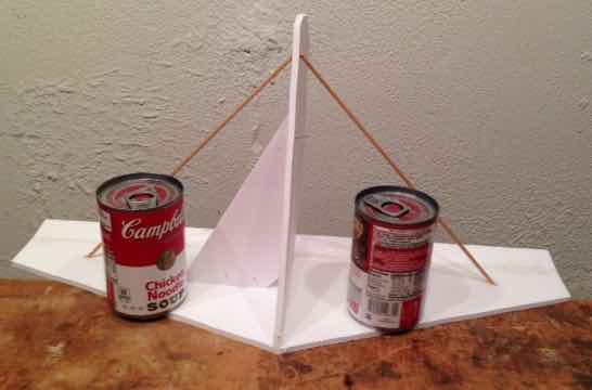
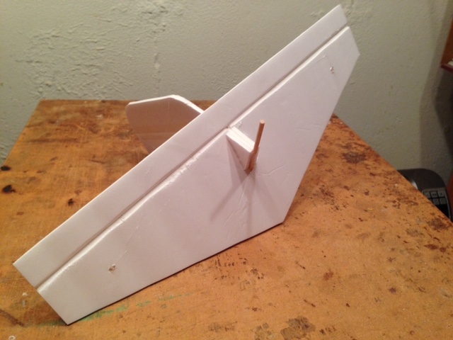
Assembling the Spars
The vertical part of the spar folds up onto the top of the Spar floor and is glued and pinned into position. The 90 degree foam board triangle is used as an aid to pin the vertical part of the Spar into position.
1. Prepare a flat surface for the Spars that is not on the building surface. That alternate surface is used to set them on while they are weighted and the glue is drying.
2. Complete the assembly of both Spar parts.
This Spar was moved to the alternate surface after the photo was taken.
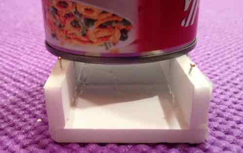
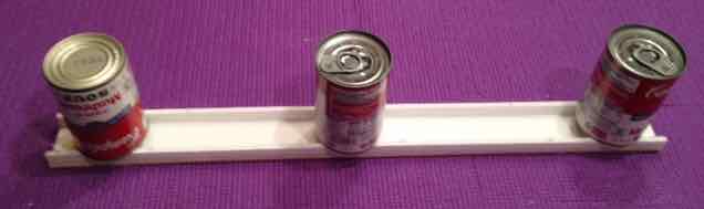
3. Move the glued spars to their "drying surface" and weight them. Full soup cans work well as weights.
The procedure remains the same for joining the pages but DO NOT CUT OUT THE VERTICAL STABILIZER CUTOUT ON THE TEMPLATE!
Required Items: the joined Fuselage Floor and Rear Top template pages, the same DTFB the Spars Parts were cut from, single edge razor blade, X-ACTO knife w/#11 blade, 48" straight edge, Elmer's Washable School Glue Stick, masking tape
1. Lay the DTFB on the building board. The template is aligned "as close as possible" to where the Spar Parts were cut. See the Parts Layout.
2. Flip the template over and run an Elmer's Washable School Glue Stick around the edges of the template.
3. Flip the template back over and align it on the foam board. Smooth it and press it down onto the foam board.
4. Apply the masking tape over the cutouts.
5. Cut out the slot for the Vertical Stabilizer using the X-ACTO knife and single edge razor blade. The X-ACTO knife works best for the short sides of the slot. It also works best for the tab lines at the front of the Fuselage Floor and the "V" cut at the rear of the Fuselage Floor.
6. Using the outline of each part, cut out both parts and remove the paper templates.
7. Set the parts aside and the remainder of the piece of DTFB.
The procedure remains the same for joining the pages.
Required Items: the joined V-Stab template pages, the same DTFB the H-Stab was cut from, single edge razor blade, X-ACTO knife w/#11 blade, 48" straight edge, Elmer's Washable School Glue Stick, masking tape, 1/16" drill bit, sanding block, strapping tape, scissors, 1/4" diameter shank Phillips screwdriver
1. Cut out the Battery Tray Rail template and the two Sub-Fin Doublers leaving a 1/4" border around each part. Set those templates aside with the other templates. Be sure there is tape running across the joint of the two parts of the Battery Tray Rail template.
2. Cut the dashed lines on the two parts of the V-stab template using the 48" metal rule and a single edge razor blade.
3. Cut out both parts of the Vertical Stabilizer leaving about a 1/4" border around the remainder of the actual V-Stab template.
4. Align the two parts of the Vertical Stabilizer along the short dashed lines on each section of the V-Stab and tape them together. There is no overlap between the two template parts.
5. Lay the piece of foam board with the Horizontal Stabilizer cut out, back on the building surface with the cutout on the left.
6. The Vertical Stabilizer "sort of" parallels one angled edge of the Horizontal Stabilizer from the top. See the Parts Layout.
7. Flip over the V-Stab template. Run an Elmer's Washable School Glue Stick along the edges of the V-Stab template as well as some crosses of glue through the middle.
8. Position the V-Stab template on the foam board and press it down.
9. Hand drill a 1/16" pilot hole at the point marked on the template.
10. Use the 1/4" diameter shank Phillips screwdriver and same method to create the hinge between the Vertical Stabilizer and Rudder as was used for the Horizontal Stabilizer and Elevator.
11. Cut out the V-stab part outline. The curved lines on the Rudder are more easily cut using the X-ACTO knife with a #11 blade.
12. Remove the paper template.
13. Continue by following the procedure for making the hinge that was used for the hinge between the Horizontal Stabilizer and Elevator.
14. Flip the V-Stab over and run an 8" piece of strapping tape over the hinge line. Start about 1/2" from the top of the V-Stab.
The procedure remains the same for joining the pages except that there are five printed pages. There are NO masking tape Cutouts on these pages.
Required Items: the joined Fuselage sides template pages, the two previously used pieces of DTFB, single edge razor blade, X-ACTO knife w/#11 blade, 48" straight edge, masking tape, 1/16" drill bit, sanding block, packaging tape, scissors, glue, rag, 3/16" diameter shank Phillips screwdriver, pen, 2 Hitec HS-53 servos, straight pins, sanding block, 'L' square, weights
1. Cut out the Battery Protector template leaving about a 1/4" border and set it aside with the other templates.
2. Cut out the Fuselage sides template leaving about a 1/4" border all the way around it. Set it aside.
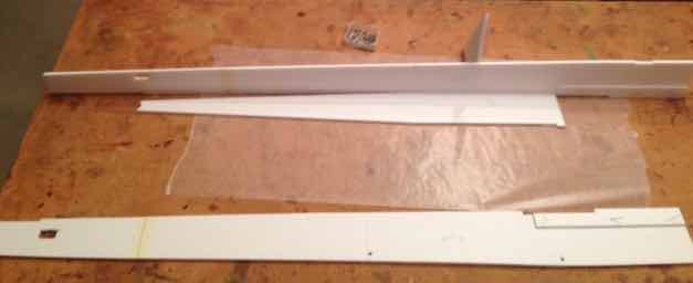
3. Lay the two previously used pieces of foam board on the building surface so that the H-Stab cutout is to the right, as shown in the photo.
4. Butt the other piece of previously used foam board to the left of it as shown in the photo.
5. Align the bottom of the two pieces and weight them down so that they don't move out of alignment while they are being taped. Hint: For a cleaner butt joint, true the two mating edges of the foam board with the 'L' square.
6. Run packaging tape, centered over the seam, between the two pieces of foam board where the Fuselage sides are to be cut from.
7. Turn the joined pieces over so that the H-Stab cutout is on the left and the straight bottom is toward the builder.
8. Position the foam board so that glue can be applied into the seam between the two pieces.
9. Apply the glue into the seam area and wipe with a finger, leaving only a small amount of glue in the joining area.
10. Lay the two pieces of foam board back on the building surface and wipe any excess glue off the foam board joint.
11. Run a piece of masking tape over the seam. That will keep the Fuselage Sides' template from sticking to the joint.
12. With a few pieces of masking tape, tape the Fuselage template to the foam board with the tape on the unused foam board and template border. The Left Fuselage side should be toward the bottom. There should be about a 1/2" between the front of the template and the right edge of the foam board. There should also be about a 1/2" between the bottom of the template and the bottom of the foam board. See the Parts Layout.
13. By hand, use the 1/16" drill bit to open the 4 pilot holes for the wing hold down dowels.
14. Create the vertical crease lines across the Fuselage sides using the 3/16" diameter shank Phillips screwdriver. They are noted by the long dashed lines. The creases don't need to be too heavy. They are there to encourage the Fuselage sides to bend at that point.
15. Cut the lines for the sides and bottom of the slot for the Velcro in the Left Fuselage side with an X-ACTO knife.
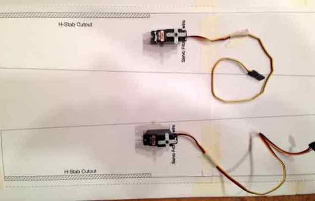
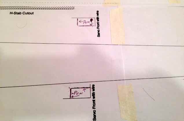
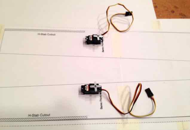
16. Set the servos in place along their respective lines. The end of the servo with the wire goes towards the front of the Fuselage sides.
17. What becomes the bottom servo side is set on the servo guide line. Draw a pen line around the two servo sides that have no alignment marks. Note the pen line mark positions in the photo. Yes, the left side servo ends up near the top of the Left Fuselage side.
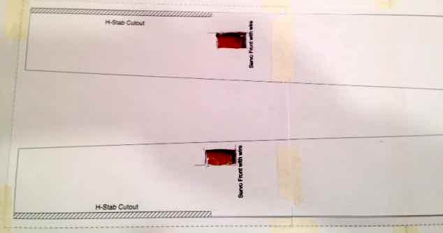
18. Cut out the slots for the servos using an X-ACTO knife and remove the foam board from the slots.
Photo shows the servos setting in their slots
19. Trial fit the servos. They will actually be positioned on the outside of the Fuselage sides during the installation of the onboard radio components. Set the servos aside.
20. First cut all of the short vertical lines for the H-Stab, Bottom Rear tab slot and Landing Gear slot. DO NOT CUT THE VERTICAL LINES FOR THE FRONT AND REAR OF THE FUSELAGE YET.
21. Cut all of the horizontal lines for the H-Stab, Bottom Rear tab slot and the Landing Gear slot.
22. Cut the horizontal outline lines for the Fuselage sides. Do NOT run the cuts through the right edge of the foam board. The long, horizontal cuts run from the rear Fuselage side vertical line to just past the front Fuselage side vertical line.
23. Cut the two diagonal lines.
24. With the single edge razor blade, cut the vertical line at the front of the Fuselage sides.
25. Cut the vertical line at the rear of the Fuselage sides.
26. Set the two large pieces of foam board aside.
27. Remove the template paper and the cutouts from the Fuselage sides.
28. Write the word Left on the inside of the left fuselage side and the word Right on the inside of the right fuselage side.
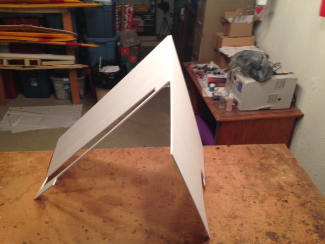
29. Lay the fuselage sides aligned one on top of the other, with the inside surfaces facing each other.
30. Stand them vertically on top of the building surface with their bottom thicknesses on the building surface.
31. Use the L-square to align both sides at the front of the fuselages. Run a straight pin through the fuselage sides somewhere near the front. Keep the sides as vertical as possible.
32. Add several more pins through the Fuselage sides to hold the sides in alignment. Note: When aligning and sanding the rear of the fuselage top, place a piece of scrap foam board (the 'V' piece from the between the left and right fuselage sides works well) into the cutout for the horizontal stabilizer so that the cutouts align. Leave the scrap foam board there while sanding the top thicknesses of the fuselage sides.
33. Use a sanding block, with medium sand paper, to sand the fuselages sides top and rear to identical shape. Note: Be mindful of the pins sticking through the foam board. If you prick yourself, you will leave blood on the outside of the foam board. Besides being unattractive, it hurts!
34. Separate the fuselage sides by removing the pins.
The terms "top" and "bottom" are relative. Top, in this instance, means away from the viewer when the pages are laying flat on the building surface. Bottom means closest to the viewer when the pages are laying flat on the building surface.
Remember to cut out the Masking Tape Cutouts as the pages are being trimmed to be joined but DO NOT cut out the small, vertical triangles near the Wing Center Line on WT-D & WT-E when cutting the template. The triangles are cut out on the foam board to allow for the dihedral angle. There is a small portion of these triangles found on the bottom row of template pages as well.
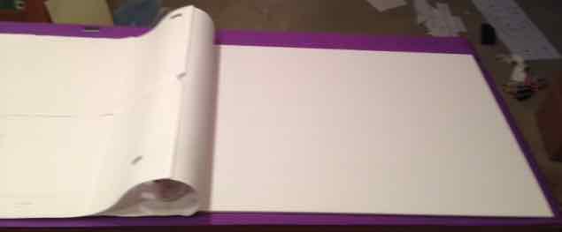
Wing (Top row of pages)
Save, then Print:Wing Top Template Row There are 8 pages to be joined.
1. A 60" long working surface is required to assemble the wing template rows.
2. Assemble the top row of the wing template starting with the page that contains the right wing tip, page WT-H. It only needs the masking tape cutouts cut out. The alignment marks have alphabetic letters by them. Cut of the right side of WT-G and cut out the cutouts for the masking tape. Align WT-H to WH-G and tape together with small pieces of tape. Follow the same procedure all the way through the left wing tip template, WT-A.
The Top Row of the Wing Template Complete
3. Set the Top Row template aside
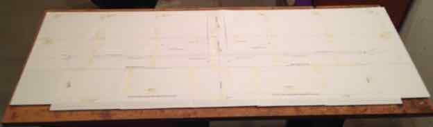
Wing (Bottom row of pages)
Save, then Print:Wing Bottom Row of Pages There are 8 pages in the bottom row.
Note: The procedure is a little different.
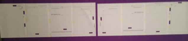
1. Using pages WB-E through WB-H, assemble them in the same manner as the top row templates. Remember to remove the masking tape cutouts. Once the four pages are assembled, use the 48" straight edge to cut across the alignment marks at the top of the joined pages.
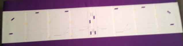
2. Assemble the remaining four pages, WB-D through WB-A starting with the page WB-D. It also has the wing's center line on it. Most of the Wing Center Line Mark will be removed when cutting the right side alignment, alignment mark D. Once the four pages are assembled, use the 48" straight edge to cut across the alignment marks at the top of the pages.
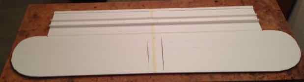
The photo shows the right wing panel pages already trimmed across the top alignment marks and the left wing panel pages ready to be trimmed across the top alignment marks.
3. Once both wing panel templates have been trimmed across the top alignment marks, align and join WT-D to WT-E with tape.
The bottom template row is complete
4. Align the bottom row of pages over the top row of pages. Start by taping the wing center line top and bottom row pages together. Be sure that the wing center line can be clearly seen. Tape the right and left end pages together so that they are aligned. Add tape to make the very large template manageable.
Required Items: Completed Wing Panel template, two new sheets of DTFB with the stickers removed, 48" straight edge, 12" straight edge (ruler), single edge razor blade, straight pins, pen, packaging tape, masking tape, sanding block, scissors, glue, straight pins, rag, 3/16" diameter shank Phillips screwdriver, metal 'L' square, old plastic credit card or gift card
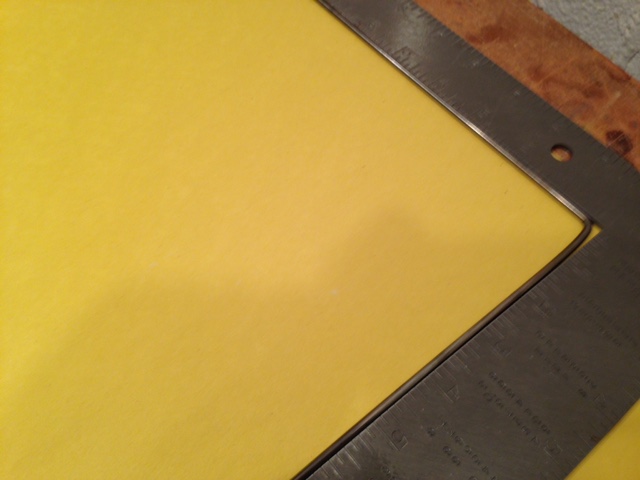
DTFB does not have square corners and the paper on the top and bottom slightly overhangs the foam.
1. Remove the stickers from the two pieces of DTFB.
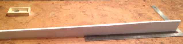
2. Using the metal 'L' square, square one end across the 20" width of each of the new pieces of foam board. Remove about 3/32" to 1/8" at the narrowest point of the angle with a single edge razor blade, keeping the blade as vertical as possible along the metal 'L' square. A sanding block can be used to align the metal 'L' square to the bottom edge of the DTFB.
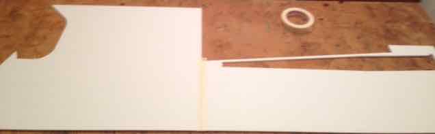
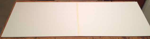
3. Butt join the two pieces along the now straight edges and align them. Once they are aligned, weight them so they can't move.
4. Run packaging tape across the seam between the two pieces of foam board. The tape should align with about 1/2 the tape on one side of the seam and 1/2 on the other. Working with two 'shorter' pieces of packaging tape is easier to manage than using one long piece.
5. Flip the foam boards over and set them so that glue can be run into the seam. Wipe the glue in the seam with a finger to spread it and remove some.
6. Lay the panels down and wipe off any excess glue with a finger. Clean the finger with the glue on it with a rag.
7. Run masking tape over the seam to keep the Wing template from sticking to it.
8. Use the 48" straight edge to mark the joint on the top of the tape between the two pieces of foam board with a pen.
9. Align the center line of the Wing template over the DTFB joint and weight the template in place. (Three full soup cans work well.) The entire wing template should fit on the joined DTFB. It is possible that Line 0 might not be on all of the foam board at one end. That is not critical. The critical factor is that Line 9 IS all on the DTFB and can be cut straight. The plans may 'appear' to be cocked or crooked on the foam board. That doesn't matter as long as the template wing center line is on the line that is the joint between the two pieces of foam board.
10. Once satisfied with the Wing template alignment, flip the template back over the cans holding the alignment. Apply Elmer's Washable School Glue Stick to the exposed foam board. Flip the template back into place and press down, smoothing it to the foam board. Apply masking tape to all of the masking tape cutouts on that side of the template.
11. Remove the weights. Flip the other side of the template back over to expose the other piece of foam board. Apply Elmer's Washable School Glue Stick to the exposed foam board. Flip the template back into place and press down, smoothing it to the foam board. Apply masking tape to all of the masking tape cutouts on that side of the template. The Wing template is now affixed to both pieces of foam board.
The wing template is affixed to the foam board
12. Using the 48" metal rule as the guide and a single edge razor blade, cut along Line 9 at the top of the foam board to remove the excess foam board. There won't be much to remove. Start the cut from the Wing Center Line and go to one edge. Repeat and go to the other edge. Discard the paper and foam board that was cut off.
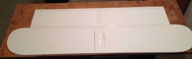
13. Cut out the rectangular areas on each side of the wing. First cut the horizontal line that runs to the edge of the DTFB and is located just below Line 5. Next cut the vertical line. Repeat for the other side. Set the rectangles aside. They will be used later.
14. Cut out the wing tips using the X-ACTO knife with a #11 blade.
15. Use a pin to make a hole at each end of Line 3 about 1/2" from the end of line. The place where the pin pricks go is shown on the templates. They only need to break through the top paper. The holes are used to align the straight edge to draw line 3 on the Wing foam board after the Wing template is removed. Wiggle the pin a little in the pin prick to make the hole more visible when the template is removed.
16. Cut out the two small, vertical triangular cutouts that are 1-7/16" from the Wing Center Line. Remove the cutouts.
17. Crease Lines 7 and 8 with a 3/16" diameter shank Phillips screwdriver. The lines don't need to be too heavy. The creased lines provide a "bending point" for the top of the airfoil. The lines are longer than the 48" straight edge. Start from the Wing Center Line and crease to each edge.
18. Also crease the long dashed vertical lines between Line 2 and 5 that are 1-7/16" from the Wing Center Joint. These creases help when forming the wing dihedral.
19. Cut off the foam board all the way across Line 0. Discard the cut off. Don't worry if the straight edge is doesn't follow Line 0 exactly. Align both ends and make the cut.
20. Cut Lines 5, 1 and 2, in that order, about 3/4 of the way through the foam. Run an old credit card or plastic type gift card through these lines. The idea is to cut through the top paper and foam but not the paper underneath the foam that is lying on the building surface. Don't worry if the straight edge does not follow the printed lines. Use the marks on each side of the printed template as the guide marks for these cuts.
21. Place a very shallow cut all the way across Lines 4 and 6. The cut should only be deep enough to remove the top paper. Peal the top paper off the top of the foam board between Lines 4 and 6. That exposes the foam.
22. Remove the paper Wing template from the foam board and discard the template.
23. Use a pen and the 48" straight edge to draw Line 3 on the foam board using the pin prick holes to align the straight edge.
24. Open a channel between Lines 1 and 2 leaving only the paper on the bottom of the channel.
To understand the 'channelling' process used to remove the top paper and foam between Lines 1 and 2, view about 10 seconds of this FliteTest video.
As demonstrated in the video, remove the foam and top layer of paper between Lines 1 and 2.
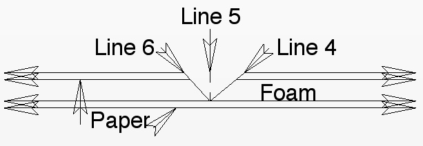
25. A double bevel is made between Lines 4 and 6. 60 seconds of this video from Flite Test demonstrates the concept of a double bevel. Instead of using a knife to cut the bevels, use the sanding block and sand the bevels between Line 4 and Line 5 and Line 5 and Line 6.
The diagram shows the bevels from a side view. The two bevels form a 'V' shape.
26. To create the bevels, lay the foam board back over itself and sand the first bevel using Line 6 as a guide for the angle. Note how the area to be sanded is close the building surface edge. This allows the sanding block to be used at an angle to create the bevel. Start off with circular motions of the sanding block and finish with horizontal strokes to create the bevels.
27. Flip the wing panel over and sand the second bevel using Line 4 as the guide.
28. After completing the bevels, lay the foam board with the top surface of the wing up. You cannot see Line 3 on the top surface. It is on the bottom surface.
29. Run packaging tape along the seam created by the leading edge, Line 9. A couple of shorter pieces are easier to handle than one long piece of tape.
30. Trim the ends off the tape and cut any tape overlapping the triangles out.
31. Flip the wing panel back over so that the inside surface, with Line 3 showing, is facing up on the building surface.
32. Lay the straight edge along Line 7. Hold the straight edge down, slide a hand under the panel and lift up on the panel. Move the straight edge as necessary and lift all the way across the line. Only a little pressure needs to be used. This pre-bending is encouraging the airfoil to take shape.
33. Repeat the process with Line 8.
34. Put a thin layer of glue on the foam board between Line 0 and Line 1 and spread the glue thinly with a finger. Wipe the finger on a rag.
35. Fold the glued piece over and pin it to the rest of the inside of the wing. This forms the rear spar.
36. Using a 3/16" shank Phillips screwdriver, continue the creases that are already between Line 5 and 2 across what is now the top of the rear spar.
37. Remove the pins from the two spars that have been setting aside under weights.
38. Prepare a place to set the wing after the next step. Setting the wing aside on another flat surface clears the work surface to continue other work. (I used my basement floor.)
39. The spar aligns with its front on Line 6 and with the notched end of the spar aligned with the Wing Center Line. The point of the 'V' notch in the Vertical Spar aligns with the crease line between Line 5 and Line 2. The other spar aligns to the 1st spar and along Line 6.
40. Get the spars and remove the pins. Trial fit both spars in place to check their alignment.
41. Thinly spread glue on the bottom of one spar, align it with Line 3 and the Wing Center Line. Press the spar down and pin it in place. Repeat for the other spar.
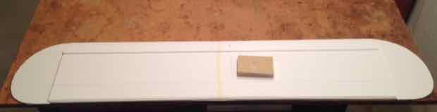
Both the rolled over rear spar and main spar can be seen in this photo.
42. Move the wing, completed to this point, to another flat surface and place weights on the Vertical Spars.
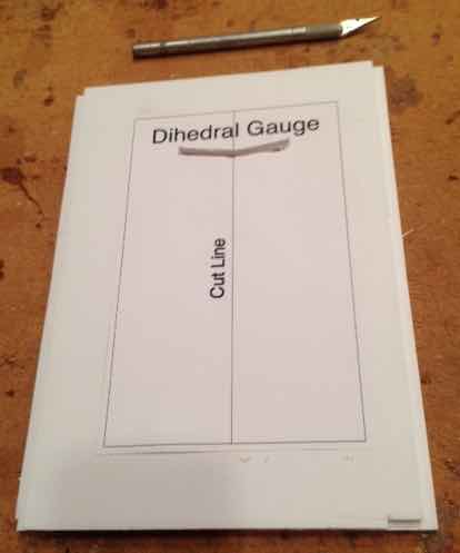
Required Items: the two foam board rectangles cut from the wing, the Dihedral Gauge template, glue, Elmer's Washable School Glue Stick, single edge razor blade, X-ACTO knife w/#11 blade, rag
1. Cut out the Dihedral Gauge template, leaving about a 1/4" border around it.
2. Laminate the two rectangles together to create a double thickness of foam board. Spread glue with a finger on one side of one of the rectangles. Press it over the other rectangle.
3. Use an Elmer's Washable School Glue Stick to glue the template onto the face of the laminated rectangles.
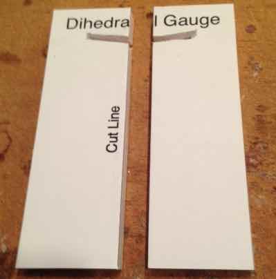
The 'V' slot has been cut.
4. Use the X-ACTO knife to cut out the 'V' slot in the template.
The Dihedral Gauge set is completed, but the template is still attached for the photo.
5. Cut out the outline of the Dihedral Gauge and then cut the vertical center line to separate the gauges. That creates a Dihedral gauge for each wing panel.
6. After removing the template paper, set the Dihedral gauges aside.
Required Items: previously cut parts templates, the foam board the H-Stab was cut from, Elmer's Washable School Glue Stick, straight edge, single edge razor blade, X-ACTO knife w/#11 blade
Several parts templates were previously created and set aside. Cut the parts out of the templates and follow any specific directions about cutting the part. Use the Parts Layout as a general guide.
The templates are affixed to the foam board with an Elmer's Washable School Glue Stick in their relative position.
The Parts Cut Out
The photo shows the parts cut out and the part of the foam board they were cut from. It also demonstrates why their position is relative. The paper templates were removed after the photo was taken.
1. Battery Tray Rails (Horizontal and Vertical are in reference to the way the way the template is laid onto the foam board.)
Cut the two short vertical lines for the Landing Gear cutout. Cut the 2 short horizontal lines for the Landing Gear cutout. Cut the three long horizontal lines. Cut the two vertical end lines. Set the parts aside.
2. Hatch and Front Top crosspiece Cut the vertical line between the Hatch and Front Top piece. Cut the two horizontal lines. Cut the two remaining vertical lines. Set the parts aside.
3. Battery Tray Use the X-ACTO knife to cut the Strap Slots. Cut out the Battery Tray. Write the word Front on the end where FRONT is printed on the template. Set the part aside.
4. Rear Front Top 1 & 2 Crosspieces Cut the 3 vertical lines. Cut the 2 horizontal lines. Set the parts aside.
5. Sub-fin Doublers Cut out the 2 Sub-fin doublers. Set them aside.
6. Battery Protector Cut out the Battery Protector outline. Remove the template and set the part aside for now. (Ignore the mount drawing on the battery protector template.)
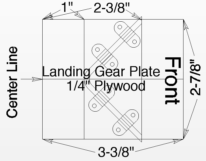
Required Items: 3-3/8" x 2-7/8" x 1/4" plywood landing gear plate, 1/8" music wire landing gear legs, 12" ruler, electric hand drill, 5/64" drill bit, pen, 1 set of Dubro Nylon Large Landing Gear Straps, flat tip screwdriver that fits the heads of the screws in the Landing Gear Straps package, safety glasses
If the Landing Gear Plate, Firewall and 1/8" music wire gear legs were not ordered from Ken, click here for the complete construction details.
1. Draw a horizontal center line on the Landing Gear Plate as shown in the diagram. It is 1-7/16" from one edge of the plate.
2. Draw the two vertical lines shown in the diagram. They are used for aligning the 1/8" diameter wire landing gear on the plate.
3. Write the word "Front" on the front of the plate for later orientation when attaching it to the fuselage bottom.
4. Align the landing gear legs on the Landing Gear Plate, as shown in the diagram. The legs of the landing gear align with the line that is 1" from the front of the Landing Gear Plate.
5. Hold a strap firmly in place on the Landing Gear Plate and over the landing gear wire. Use an electric hand drill to drill two holes for the strap screws using a 5/64" drill bit.
6. Remove the landing gear wire and strap.
7. Slightly wobble the 5/64" drill bit through the two 5/64" holes to enlarge them just slightly. A 3/32" bit is too large for the screws. Wobbling through the 5/64" holes opens up the holes just enough that the screws go in easier, but not too easy.
8. Put the landing gear wire and strap back into place and screw the strap into place. When the screws are screwed all the way in, they will poke through the other side of the plate. That's fine, but be aware of that to keep your fingers from snagging on them.
9. Hold another strap in place and drill out the 5/64" holes.
10. Remove the strap and do the wobble.
11. Do that for the remaining two strap holes.
12. Screw all of the straps firmly and completely down.
13.Remove the straps and landing gear legs. Set them aside.
14. Set the Landing Gear Plate and wire landing gear aside.
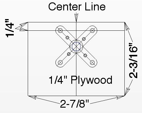
Required Items: 2-7/8" wide x 2-3/16" high x 1/4" thick plywood Firewall, the DTFB Battery Protector, Dubro 4-40 blind nuts, Dubro Socket Cap Screws 4-40x3/8, electric hand drill, 1/8" drill bit, the Cobra motor's cross mount, 5/16" drill bit, pen, 12" ruler, safety glasses
1. Draw a line parallel to the top of the firewall 1/4" down from the top. The top motor cross mount holes are centered on this line.
2. Draw a vertical 2-3/16" long center line 1-7/16" from one edge. The center hole of the motor's cross mount is "eyeball" centered on the center line.
3. Lay the motor's cross mount on the plywood, and using the guide lines, mark all 5 hole centers.
4. Use an electric hand drill to drill out all 5 holes with a 1/8" bit.
5. Drill out the pre-drilled center hole with a 5/16" bit to open it up more.
6. Fasten the motor's cross mount to the firewall using the 4-40 bolts and blind nuts.
7. Spin the blind nuts onto each bolt until they are touching the back of the Firewall. Hint: It is easier to start the blind nut into position with a longer 4-40 cap screw, replacing the longer cap screw and then finish tightening the blind nut into the wood with the 3/8" long 4-40 cap screw.
8. Tighten the bolts snugly. This pulls the blind nuts firmly into the wood.
9. Remove the move the motor mount and return it back to the box the motor came in.
10. Hand screw the 4-40 cap screws into the blind nuts in the firewall.
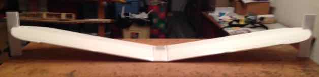
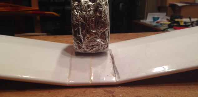
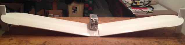
Required Items: the wing, glue, straight pins, weights
1. Remove the pins from all of the spars.
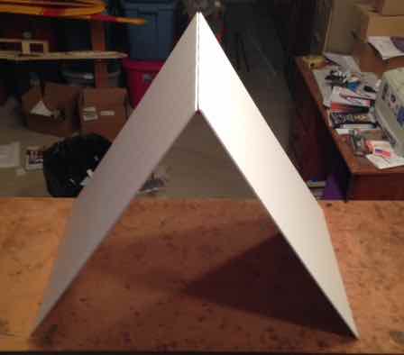
2. Lay the foam board top of the wing over the spars until the trailing edge reaches the building surface. There should be no binding or cracking heard coming from the leading edge. Don't force the panel down. If cracking or popping is heard, sand the leading edge bevels more if necessary. An 'airfoil' should be the result.
3. Once the foam board top lays nicely, while touching the spar verticals, and the rear spar, open the wing.
4. Run glue into the leading edge angle and the creases in Lines 7 and 8. Run your finger down lines 7 and 8 to force the glue into the creases. Wipe excess glue on a rag.
5. Run a bead of glue onto the top of the Vertical Spars and the rear edge of the rear spar. DO NOT spread with a finger.
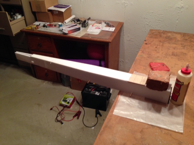
6. After applying the glue, set the wing on another flat surface to free up the building surface.
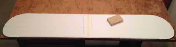
The photo was taken on the work surface and then moved.
All kinds of weights were used, including bricks.
7. Fold the top of the wing over the spars with the trailing edge laying on the flat surface. Very heavily weight it down.
Required Items: Left and Right Fuselage sides, Battery Tray Rails, Fuselage Bottom Floor, Fuselage Top Rear, glue, 90 degree triangle, straight pins, rag, wax paper, weights, 3/16" x 36" dowel, 1/8" x 36" dowel, 11/64" drill bit, typical craft type hot glue gun and hot melt glue sticks, toothpicks, kitchen-type cutting board, X-ACTO saw blade, 4 straight craft sticks, 12" ruler, Landing Gear Plate
Note: When using any kind of glue, and the parts are to set on a flat surface, protect that surface with wax paper.
1. On a cutting board, use the X-ACTO saw blade to cut two 3/16" by 4-7/8" wooden dowel pieces for the wing hold downs. Cut one 3/16" by 3-3/4" wooden dowel piece for the tail skid. Set them aside.
2. Cut two 1/8" by 11-1/4" wooden dowel pieces. They are used on the "tail feathers" as braces. Set them aside.
3. Cut the rounded end off each of the 4 craft sticks to square one end.
4. Measuring from the squared end, cut each stick to 2-3/4" long using an X-ACTO saw blade.
5. At the 1-3/8" point on each stick, cut about half way through the 'face of the stick' so that when turned over from the cut, and laying flat, the stick can be bent, or cracked, upwards at an angle from the cut. These 'sticks' are the rubber band protectors. Set them aside.
6. Lay the Fuselage sides, with the insides of the Fuselage sides facing up on the building surface. Trial fit the Battery Tray Rails to the inside front of each fuselage side. Use glue to laminate, by spreading glue thinly on the back of the Battery tray rail, a Battery Tray Rail to each Fuselage side.
To position the Battery Tray Rail accurately, use the Landing Gear Plate and sanding block as alignment guides.
Trial fit a Battery Tray Rail into position so that the Battery Tray Rail aligns with the bottom of the fuselage and the Landing Gear Plate cutout.
Remove the Battery Tray Rail, flip it over, and spread glue thinly on the 'backside'.
Wipe off the excess glue with a finger and wipe the finger on a rag.
Align the Battery Tray Rail. Press the glued Battery Tray Rail into place, adjust and pin if necessary.
7. Set that fuselage side aside on the building board.
8. Repeat for the remaining fuselage side.
9. Lay wax paper, at least as long as from the front of the Rear Fuselage Floor to its end, on the building surface where the Fuselage sides are glued onto the outside of the Fuselage Floor.
10. Plug in the hot melt glue gun.
11. By hand, drill out the 4 wing hold down 1/16" pilot holes in the fuselage sides with an 11/64" bit. (Yes, that is slightly undersized.)
12. Use one of the wing hold down dowels and poke it through each of the 4 11/64" holes.
13. Apply glue to the thickness of one side of the rectangular part of the Fuselage Floor only where it will attach to the fuselage side and on the top of its tab. Set that part on the wax paper.
14. Join a Fuselage side and the Fuselage Floor. Pin the 90 degree triangle to the fuselage side. Be sure that the Fuselage Bottom Floor tab is 'pulled' all the way back into its slot.
15. Using the 90 degree triangle to maintain 90 degrees, hot glue the joint between fuselage side and Fuselage Floor rectangular area.
16. Remove the 90 degree triangle from the fuselage side.
17. Lift the joined pieces and put glue on the thickness on the other side of rectangular fuselage floor.
18. Use the same process to glue on the other fuselage side to the Fuselage Floor.
19. Poke the wing hold down dowels through their holes and glue into place. There should be about 1" of dowel protruding from each side of the fuselage.
20. With the wing hold down dowels in place, doing one fuselage side at a time, make adjustments to make sure the fuselage sides are at 90-degrees to the building board using the 90 degree triangle.
21. When satisfied that that fuselage side is square to the Fuselage Floor, use the hot melt gun to put dabs of glue on the wing hold down dowels, inside and outside the fuselage.
22. Repeat for the other Fuselage side.
23. Unplug the hot melt glue gun.
24. Remove any pins from the Landing Gear Doubler. Temporarily, using pins through the fuselage side to hold it in place, set the 2-1/2" width of the Battery Protector vertically across the fuselage with its bottom resting on the Battery Tray Rails about one inch or so from where the firewall will be epoxied to the front of the fuselage. The user built right triangle can be used to align the Battery Protector across the fuselage. This holds the front end in alignment from gluing on the Firewall. The protector will be below the Fuselage sides and no pins should be above the fuselage side.
25. One side at at time, apply glue to the remainder of the Fuselage Floor. Use a toothpick to spread the glue where your finger can't reach.
26. While holding the Fuselage Floor flat on the wax paper on the building surface, pin the Fuselage side to the Fuselage Floor. Hint: Putting the pins through the bottom of the fuselage side into the fuselage floor is easier with the parts right at the edge of the building surface. Repeat for the other side.
27. Glue on the Fuselage Top Rear piece. The front of the Top Rear piece aligns with the creases in the fuselage sides. Be sure the Fuselage sides align with the outside edge of the Top, Rear part. Push and Pull as necessary before pinning in place.
28. Inspect the Fuselage joints. Move or add pins as necessary to get a tight fit between the Fuselage Floor and the Fuselage sides.
29. To clear the building surface for more construction, on another flat surface, turn the fuselage upside down on wax paper.
30. Weight the front of the fuselage so that the front top of the fuselage is resting on the wax paper on the new flat surface.
31. Epoxy the prepared Landing Gear Plate into position.
32. Epoxy the prepared Firewall to the front of the fuselage. The top of the Firewall rests on the flat surface.
33. Align the fuselage sides to the Firewall and press into position.
34. Clean hands with denatured alcohol, wipe on a rag, wash thoroughly.
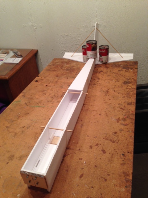
The photo was taken at the end of the day, so the fuselage was on the bench.
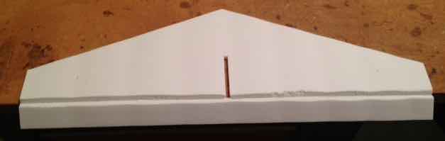
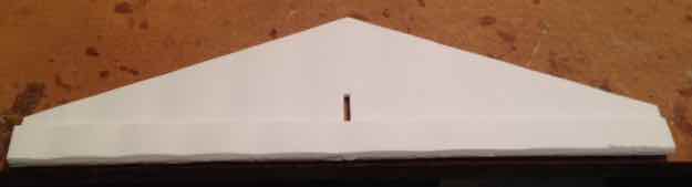
Tail feathers is a term used to describe the horizontal stabilizer and elevator in combination with the the vertical stabilizer and rudder. The horizontal stabilizer and elevator remain one piece in this construction, as well as the vertical stabilizer and rudder. To simplify notation, they are called H-Stab and V-Stab respectively. Tail feathers is used to describe both assemblies once they are joined together.
Required Items: the foam board pieces for the H-Stab & V-Stab, glue, hot melt glue gun, user built foam board triangle, straight pins, weights (soup cans work well), rag, strapping tape, scissors, 2 Sub-fin Doublers, two 1/8" x 11-1/4" dowel pieces
1. Plug in the hot melt glue gun.
2. Hand drill out the pilot holes in the H-Stab and V-Stab with a 1/8" drill bit to open them up.
3. Trial fit the H-Stab and V-Stab together.
4. Place two weights, like full soup cans, within reach.
5. Set the Tail Feathers on the building surface with the tape hinges on top of the H-Stab. The assembly should overhang the building surface to allow the sub-fin of the V-Stab to pass through. The H-Stab should have the strapping tape hinges on top.
6. Weight the H-Stab into a position that allows for the V-Stab Sub-fin.
7. Remove the V-Stab and apply glue to the bottom of the front of the V-Stab that sets on the H-Stab.
8. Put the V-Stab into position with the center of the thickness of the V-Stab foam board aligning with the point on the front of the H-Stab. Place a pin at the front of the V-Stab where it joins the H-Stab at the point.
9. Pin the user built 90 degree triangle to the H-Stab and V-Stab at 90 degrees.
10. Run hot melt glue along each side of the joint between the V-Stab and H-Stab. Try not to get any hot melt glue right at the joint where the end of the fuselage sides come together.
11. Poke one of the 1/8" dowel pieces through one of the holes in the H-Stab. Angle it, and adjust it, so that it will go about 1/2 way into the hole in the V-Stab when the V-Stab is at 90 degrees to the building surface. The 90-degree triangle should be still in place.
12. Repeat for the 1/8" dowel strut on the other side.
13. When satisfied that both sides are holding the V-Stab at 90 degrees to the H-Stab, hot melt glue the dowels into place.
14. Remove all of the pins and the 90-degree triangle and weights from the H-Stab. Set the triangle aside.
15. Lift the Tail Feathers off the building surface and add a few more 'blobs' of hot melt glue to the struts.
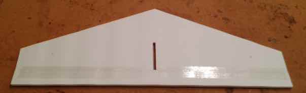
16. Glue the 3/16" by 3-3/4" wooden dowel tail skid in place.
17. Run hot melt glue along the joint between the sub-fin and dowel.
18. Put a 1" piece of strapping tape over the dowel from one side of the V-Stab sub-fin to the other.
19. Use a thin film of glue to laminate the Sub-fin Doublers to each side of the Sub-fin.
Note the glue 'blobs' on the bottom of the 1/8" dowel holes.
20. Hot glue the joint between the bottom of the H-Stab and the Sub-fin Doublers and along the Sub-fin Doublers and the tail skid.
Required Items: the fuselage, the completed tail feathers, battery protector, battery tray, glue, hot melt glue gun, straight pins, weights, single edge razor blade
Note: This step can be started once the epoxy has cured on the Firewall and Landing Gear Plate. The pins in the rear of the fuselage may be left in if the glue as not set yet.
1. Set the fuselage back on the building surface.
2. Remove the Battery Protector piece and all of the pins in the rear of the fuselage, unless the glue has not had enough time to dry.
3. Plug in the hot melt glue gun.
4. If any of the Rear Top Fuselage piece extends beyond the rear of the fuselage, trim it off with a single edge razor blade.
5. Glue and pin the Battery Tray in place with the slots for the battery strap closest to the Firewall. The tray butts against the Firewall. The glue is applied, and smeared, to the the sides, front and bottom of the Battery Tray where it sits on the rails.
6. To allow for some epoxy being in the joint between the fuselage sides and the firewall, sand the front vertical edges of the battery protector so that it fits flush against the firewall.
7. Hold the battery protector in place and run a 5/16" drill bit through the battery protector by hand through the 5/16" firewall hole.
8. Glue and pin the Battery Protector to the Firewall, fuselage sides and battery tray. Be sure the protector is even with, or just below, the Firewall. Press the protector hard against the firewall to 'indent' the blind nuts.
9. To help the Velcro that holds the Hatch down stick in the slot, run some glue in the slot and spread it with a finger into a thin coat.
10. While holding the fuselage in your hand, temporarily slide the tail feathers onto the rear of the fuselage. Be sure the 'V' of the horizontal stabilizer goes into the 'V' slot at the end of the Fuselage Floor. Remove the tail feathers.
11. Apply glue, and smear it with a finger, to the bottom thickness of the Fuselage sides where the Tail Feathers are glued on and on the 'V' in the fuselage floor.
12. Slide the Tail Feathers into position in the 'V' of the Fuselage Floor and press the Tail Feathers to the bottom of Fuselage. Pin the Tail Feathers into place in the 'V'. Push the pins all the way in so that the Tail Feathers can set flat on the building surface.
13. Turn the Fuselage and Tail Feathers assembly over.
14. Set, and weight, the Tail Feathers off the end of the building surface so that the fuselage can set on the building surface in front of the Tail Feathers. Also weight the end of the Fuselage just in front of the V-Stab.
15. Run hot melt glue along the H-Stab and fuselage joint on both sides, moving weights as necessary.
16. Glue and pin the joint between the V-Stab and fuselage.
17. Run hot melt glue along the joint between the Rear Top fuselage piece and the V-Stab. Be sure everything has stayed 'square' during this process.
VERY IMPORTANT! The glue on the wing must be absolutely dry before continuing.
Required Items: wing dihedral gauges, epoxy, partially completed wing, large, flat tip screwdriver (1/4" to 5/16" blade width), X-ACTO knife w/#11 blade, several weights (bricks are best if you have a couple), epoxy, round toothpick to mix epoxy, something to mix epoxy on, denatured alchohol (to clean hands), rag, masking tape
The glue, used to glue the top of the wing to the spars, MUST be dry before setting the Dihedral angle for the wing. If it has not had adequate time to dry, start working on the second airframe.
1. Lay the partially completed wing on the building board.
2. Use a single edge razor blade and cut through the leading edge tape at the front of the triangle cut outs towards the leading edge of the wing.
3. Use a fairly broad, flat tip screwdriver and draw the screwdriver at a 45 degree angle on all the inside edges of the triangle cutout in both wing panels. The angles allow the top of the cutout to come together neatly.
4. Weight the wing center section with a brick or other very heavy object that will sit on the center section and allow both panels to be 'pulled' up while holding down on the weight. Lift a wing panel using the wing tip and check how high it will go. The wing tip must move up higher than the slot in the dihedral gauge. Keep working the slot between the center section and each wing panel with the flat tip screw driver and X-ACTO knife until it can easily be held up by hand a higher than where it will fit in the dihedral gauge slot at the panel's highest point, line 8 nearest to the trailing edge, while the center section remains flat on the building surface. The flat tip screwdriver can also be used to help increase the width of the notches in the Vertical Spar Parts and across the rear spar. This step does take a bit of trial and error to get it correct. With the brick on the center section, lifting up on both wing tips, trying to raise the brick also helps. You can't actually lift the brick.
5. Trial fit both dihedral gauges in their respective postions. Use the 90 degree triangle to make sure the dihedral gauges are 90 degrees to the building surface.
6. Remove the weight from the center section. The center section should remain close to flat on the building surface. If it doesn't, keep working the joints until it does.
7. Prepare the the other flat surface, where the wing joints are to be glued.
8. Prepare the weight/brick. Place wax paper on the weight where it will rest on the center section. Masking tape does not stick well to wax paper nor a brick. It does stick well to itself. To hold the wax paper to the brick, wrap several wraps of masking tape, lengthwise, around the wax paper and the brick. Draw the masking tape tight and stick the masking tape to itself.
9. Move the wing to the other flat surface.
10. Reinstall the dihedral gauges and center section weight. Align the gauges vertically using the 90 degree triangle, with the weight still on the center section. Another weight is placed on the front of the center section, but it is not shown in the photos.
11. Epoxy both wing panel joints along the center section and wing panels.
12. Smooth the epoxy all the way along the joint between the center section and panels with the toothpick.
The photos were taken on the building surface for better lighting, but the wing was actually moved after the photos were taken.
The photos shows aluminum foil on the brick. Wax paper is better, as the epoxy won't stick to it.
13. Allow the epoxy to cure, at least one hour.
Note: Yes, there is a lot of dihedral in this wing! Some of the angle will 'settle out' once the dihedral braces are removed.
14. Clean any epoxy off fingers with denatured alcohol and a rag and wash hands immediately.
Required Items: almost completed wing, partially completed fuselage, 4 precut craft stick wing hold down protectors, hot melt glue gun, glue, the top front piece, 2 top front rear crosspieces, the hatch, packaging tape, scissors, strapping tape, pins, 4 #64 rubber bands, sticky back hook'n-loop fastener (Velcro), 12" ruler
Note: Before proceeding, inspect the wing joints. If there are large gaps, where there is no epoxy in the joint or joints, mix some epoxy and fill the gaps. The epoxy does NOT need to cure before proceeding.
1. Plug in the hot melt glue gun.
2. Run a length of packaging tape over the top of both wing panel joints between the panels and the center section.
3. Hot glue the four craft stick rubber band protectors to the leading and trailing edges of the top of the center section and onto the top of the wing panels. One end of each of these sticks aligns with the Wing Center Lines.
4. Unplug the hot glue gun.
One rubber band is shown looped, the other still needs to be looped.
5. Loop two of the #64 rubber bands together to make a 'longer' rubber band. Repeat for the other two #64 rubber bands. (A total of 6 of these longer rubber bands are used when flying.)
6. Set the fuselage on the building board with the sub-fin and tail skid overhanging the edge of the building board.
7. Use a thin film of glue to laminate the two Rear Front Top pieces together.
8. Rubber band the wing into place using the joints between the wing center section and wing panels and the fuselage sides as a guide. Don't let the rubber bands on the front wing hold downs interfere with where the Rear Front Top crosspieces are glued on butting up to the wing.
9. Remove the paper from ONE SIDE of the laminated Rear Front Top fuselage crosspiece. Use the Hatch, setting across the fuselage, as a squaring tool for this piece.
10. Glue the Rear Top Front fuselage laminated crosspieces in place in front of the wing with the paperless side down for better adhesion. Use the Hatch to align the crosspieces, NOT THE WING. Pin in place.
11. Pin the Hatch, only on the left side, the side with the notch for the Velcro, in place, leaving a little room between its rear and the front of the Rear Front Top crosspiece.
12. glue and pin the oversized front crosspiece in place leaving a little room between it and the front of the Hatch. The overhang of the front top crosspiece is cut off later.
13. Run a 5-3/8" piece of strapping tape, centered on the right side of the Hatch edge, and roll it over onto the Right fuselage side to form the hatch hinge.
14. Remove the pins on the left side of the hatch and open it so that it doesn't get glued down from excess glue on the rear and front pieces.
15. Cut a 1-1/8" long piece of sticky back Velcro.
16. Cut each of the two sections of 1-1/8" Velcro to about 3/16" wide.
17. Place one the pieces in the cutout on the left side of the fuselage and the other piece on the hatch just above the cut out so that they will 'mate'.
18. Remove the rubber bands, wing and fuselage from the building board and set them aside.
The first airframe is completed, except for cutting off the overhang of the crosspiece at the Firewall.
Replacing the XT-60 Connectors on the Hyperon 3S 2100mAh LiPo Batteries
Required Items: 2 (or more) Hyperion 3S 2100mAh LiPo Batteries, 6" diagonal cutters, APP crimping tool, 4 APP 30A connectors with two red and two black housings, single edge razor blade, 12" ruler, tiny flat tip screwdriver
WARNING!!! REPLACE ONLY 1 LEAD AT A TIME FROM THE LIPO BATTERY!!!
Watch this video BEFORE attempting to replace the connector.
The YouTube video is titled "Installing 45A Anderson Powerpole connectors for RC applications". It demonstrates how to install APPs on a battery. The procedure is exactly the same for the 15A and 30A contacts.
IT IS EXTREMELY IMPORTANT TO NOTE THAT THE AUTHOR OF THE VIDEO ONLY SNIPS ONE POWER LEAD AT A TIME FROM THE BATTERY.
HE COMPLETES ONE LEAD BY CRIMPING ON THE APP CONNECTOR AND INSTALLING ITS HOUSING BEFORE SNIPPING THE OTHER LEAD AND REPEATING THE PROCESS. This is how it should be done!
One power lead is cut using a 6" Diagonal Cutter (wire cutter).
A wire stripper is shown in the video stripping the wire lead. A single edge razor blade can be used instead of a wire stripper. The blade can be held somewhat stationary with a bit of pressure on it while pressing on the wire and the wire 'rolled' on a work surface to cut the silicone covering.
Install the colored housing on the correct wire color. Be sure you hear a 'snap' when the connector is inserted into the housing. Sometimes a very small flat tip screwdriver can convince the connectors to seat in the housing. Try to pull the wire and connector out. It should NOT come out. If it does, keep trying until it won't come out.
Once one power lead has been completely finished and its colored housing, matching the lead's color, has been installed, the other power lead is finished using the same procedure.
For polarity protection, the housings have a 'slot' on one side of the housing and a ridge on the other. The positive and negative housings can be joined together to create a polarity protected connector.
Linking/Binding the Transmitter to the 'Receiver' and Setting Up the Radio System on the Bench
Required Items : Radio Transmitter (Tx) and 'Receiver' (Rx), 2 Hitec HS-53 servos, 2 16" servo extensions, electronic speed control (ESC), the battery to power the plane and radio system (3S 2100mAh Hyperion LiPo), 2 Anderson Power Pole connectors with a red and a black housing, the APP crimping tool, single edge razor blade, round toothpick, scissors, masking tape, 6" diagonal cutter, medium sandpaper, denatured alcohol
Note: The next step is completed with the radio system components and ESC out of the plane and on the bench.
1. Cut off the two pre-tinned power lead ends of the ESC by about 1/8" or so with the 6" Diagonal Cutter to remove the pre-soldered ends. Do NOT cut off the three bullet connectors on the ESC!
2. Strip the power leads on the ESC about 3/8" using a single edge razor blade.
3. Crimp a 30A APP connector on each power lead using the APP crimping tool.
4. Install the connector housings on the correct wire colors. Be sure you hear a 'snap' when the connector is inserted into the housing. Sometimes a very small flat tip screwdriver can convince the connectors to seat in the housing. Try to pull the wire and connector apart. If it comes apart, reinsert it and listen for the 'snap'.
5. Attach the three bullet connectors on the ESC to the three bullet connectors on the motor. The order or wire color does not matter, yet. This will keep them from shorting, should the throttle on the transmitter be moved.
Note: The following applies specifically to the Tower Hobbies 424 Radio System. If you are using a different Radio System, see Using Your Own Choice for a Radio System.
6. Reverse channel 3 of the Tower Hobbies transmitter. (See the manual that came with the radio system to see how to do that. It is just moving the switch for Channel 3 to the 'other' position.) Note: Reversing the throttle channel only applies to certain brands; Tower Hobbies, Tactic, Futaba and Hitec.
7. When using the Tower Hobbies system, plug the ESC radio connector into Channel 3 of the receiver with the black wire of the ESC lead to the outside of the receiver. Be sure it is actually plugged into Channel 3. Note: Be sure to check the user's manual for your radio brand to identify the throttle channel number for the receiver. Many brands are different.
8. Turn on the transmitter.
9. The Tower Hobbies' radio should have come with the transmitter 'linked' to the 'receiver'.
10. Check to see if the transmitter and 'receiver' are linked.
Turn on the transmitter.
Plug the power battery into its connector on the electronic speed control (ESC).
If the transmitter and 'receiver' are linked, the red light will come on and stay on in the 'receiver'. You will also hear tones from the ESC signal sounding in the motor.
11. Continue and skip to the next directions if they are linked.
If the transmitter and 'receiver' are not linked: Hold the linking/binding button down in the receiver using a round tooth pick until the LED in the receiver blinks and turns off.
Let up on the button.
The LED will come on and stay on.
The transmitter and receiver are linked.
12. Disconnect the power battery from the ESC and shut off the transmitter.
13. Attach each servo to a 16", or so, servo lead extension.
14. Plug one servo lead extension into Channel 1 (aileron) on the receiver and the other servo lead extension into Channel 2 (elevator). Note: The channel assignment numbers vary with different brands of radio systems. Check the user manual for other brands for the aileron and elevator channel numbers.
15. Turn on the transmitter.
16. Plug the power battery into the ESC.
17. Move the right stick in a circular motion on the transmitter. Both servos should be moving.
18.Disconnect the power battery.
19. Shut off the transmitter.
20. Remove the servo leads from the receiver.
21. Using masking tape, tape the connections between the servo leads and 16" servo lead extensions.
22. Put a piece of masking tape, to mark it, on one of the 16" servo lead extensions about 1" from where it will plug into the 'receiver'. (At this point, it doesn't matter which extension gets the masking tape marking.)
23. Sand each of the servos' mounting tabs and then wipe the tabs with denatured alcohol. (This allows masking tape to stick to the mounting tabs on the servos by removing the release agent from the plastic servo case molding.)
24. Wrap each mounting tab on the servos with a couple of turns of masking tape.
25. Use scissors to cut off the excess masking tape sticking beyond the servo mounting tabs.
26. Disconnect the bullet connectors between the motor and ESC.
Required Items: fuselage, radio & power systems, hook 'n loop fastener, 2 servos with 16" extensions attached, hot melt glue gun, epoxy, scissors, electric hand drill, 1/16" drill bit, 5/64" drill bit, 6" diagonal cutter, large rag
1. 'Feed' the servo extension with the masking tape marking through the servo cut out on the right side of the fuselage. The masking tape on the extension now identifies this servo as the elevator servo.
2. Insert that servo into the servo hole in the right fuselage side of the fuselage and seat the servo mounting tabs onto the foam board.
3. Draw around the servo mounting tabs with the masking tape on them.
4. Remove the servo from the servo hole with the servo wire remaining in the fuselage.
5. Using a pin, poke several holes in the area where the servo mounting tabs rest on the fuselage side. Do not remove the servo and its lead from the fuselage. Let it just 'lay' there.
6. Repeat this process for the left side of the fuselage. This is the rudder servo.
7. Plug in the hot melt glue gun
8. Mix up some epoxy and epoxy the tapped servo mounting tabs of both servos in place.
9. Place a dab of hot melt glue on each servo lug to hold them in place until the epoxy cures.
10. Unplug the glue gun.
11. Unplug ESC lead from the 'receiver'.
12. Slide the ESC and its lead to the radio under the Landing Gear Plate and into the fuselage.
13. Cut a 1" piece of sticky back hook'n loop.
14. Remove one piece of hook 'n loop fastener from the paper and stick to the back of the ESC.
15. Put the other piece of hook 'n loop fastener onto the sticky hook'n loop piece on the ESC without removing the protective paper yet from the second piece.
16. Trial fit the ESC into position. When satisfied with the position, remove the protective paper and stick the ESC to the fuselage side.
17. Cut a 3-1/2" piece of sticky back hook'n loop.
18. Remove the backing from the fuzzy strip of hook 'n loop fastener and center it side to side and end to end on the battery tray.
19. Cut two 1" lengths of the remaining 3-1/2" strip and place one piece on each power battery near what will be the rear of the power battery, where the battery leads come out of the battery shrink wrap.
20. Plug the ESC lead into the throttle channel of the receiver. That is channel 3 if using a Tower Hobbies' radio system.
21. Plug the taped servo lead into the elevator channel, which is Channel 2 of the receiver if using the Tower Hobbies' system.
22. Plug the non-taped servo lead into the aileron servo channel, which is Channel 1 on the Tower Hobbies' 'receiver'.
23. Cut a 1" length of sticky back hook 'n loop. Follow the same procedure as attaching the ESC. Attach the receiver vertically to the fuselage side with the antenna sticking up but not above the fuselage side.
24. Masking tape down the servo extensions to the Fuselage Bottom Floor and the lead from the 'receiver' to the ESC and the ESC to motor leads to any place that is convenient.
25. Set the power battery in place, but do NOT hook it up.
26. Slide the back/back hook'n loop fastener through the holes in the battery tray.
27. Wrap the back/back hook'n loop fastener around the battery to measure and then cut a section of the back/back hook'n loop fastener to become the battery strap.
28. Tighten the Velcro strap and then masking tape the bottom of the strap to the bottom of the battery tray.
29. Remove the servo arms from the Hitec HS-53 servos. This requires a very tiny Phillips screwdriver.
30. Run a 1/16" drill bit through of the hole closest to the servo arm screw in each servo arm. The holes in each servo arm will now accept the pin on the bottom of a Dubro EZ connector.
31. Attach one EZ connector to each arm through the 1/16" drilled hole. A needle nose pliers helps the clip to 'seat' the keeper.
IMPORTANT REMINDER! The prop is not on the motor yet!
32. Turn on the transmitter with all of the trims in neutral.
33. Plug in the power battery.
34. Install the servo arms so that the arm with the EZ connector is vertically towards the top of the fuselage. Try to get the arm as vertical as possible.
35. Screw in the servo arm screws on both servos.
36. Unplug the power battery and then turn off the transmitter.
37. Open the control horn package and cut the horns and screw plates apart using a single edge razor blade.
38. Screw the provided Phillips head screws about 1/2 way through plates using a small Phillips screw driver. Do both plates. This aids in screwing in the control horns later.
39. Remove the screws from the plates.
40. Attach the outer most hole in one control horn to a Dubro Rod w/Nylon Kwik Link 12" and close the link.
41. Run the pushrod into the hole of the EZ connector on the Right Fuselage side servo.
42. Move the pushrod, with the control horn attached, to the rear and hold the control horn so that the holes in the control horn align with the hinge line of the Elevator.
43. Mark the control horn's plate hole positions on the movable surface.
44. Hand drill the marked positions with 1/16" drill bit and hand drill them out using a a 5/64" drill bit.
45. Screw the control horn into its plate on the other side of the movable surface until it is snug.
46. Repeat for the Rudder on the Left Fuselage side.
47. Turn on the transmitter and plug in the power battery. There is NO PROP on the motor yet!
48. Eyeball the control surfaces to neutral and mark the pushrods, which are in the EZ connectors, at the point they need to be cut off, leaving about 1/2" to 3/4" of rod extending from the EZ connector.
49. Unplug the power battery and turn off the transmitter.
50 Remove the pushrods.
51. Snip the pushrods to the marked length using a 6" diagonal cutter. Prepare to cut the rod and then place it and the diagonal cutters under a rag, so that a the two pieces don't go flying. Cut each rod this way.
52. Reinstall the pushrods into the EZ connectors and attach them to the control horns in the outer most holes.
53. Turn on the transmitter and plug in the power battery.
54. Adjust the movable surfaces to what appears to be neutral and tighten the 4-40 set screws in the EZ connectors.
55. Check for proper movement of the elevator and rudder. The Elevator should move up when the right transmitter stick is pulled back towards the bottom of the transmitter. The Rudder should move to the right when the right transmitter stick is moved to the right. If either movement is not correct, reverse the channel for that function on the transmitter.
56. Check that the motor runs when the throttle is advanced.
57. Unplug the power battery and turn off the transmitter.
58. Use a small crescent wrench to attach the APC 11x5.5E prop to the motor.
59. Set the plane on the floor and be sure the area behind the plane is clear of anything that might blow.
60. Staying clear of the prop, turn on the transmitter, plug in the power battery while holding the plane firmly.
61. Push the throttle stick forward just enough to determine if the motor is turning in the correct direction. Air should be passing towards the rear of the fuselage. If it is not, just note it for now.
62. Disconnect the power battery and turn off the transmitter.
63. Remove the prop.
64. If the prop was rotating in the wrong direction, switch any two leads between the motor and the ESC.
65. Follow the procedure in the radio system/'receiver' instructions for setting the Failsafe. Don't skip setting up the Failsafe! Check the Failsafe by running up the throttle a little and then shutting off the transmitter. The motor should shut off. Unplug the battery.
66. Balance the prop by placing it on the the Hyperion Prop Balancer. A small piece of trimmed packaging tape can be put toward the prop tip of the light blade. Rebalance. If the light blade is still to light, REPLACE the piece of tape with a larger one. If the light blade is now too heavy, REPLACE the tape with a smaller piece. Continue until the prop is balanced. Do not reuse or just add tape. Always replace.
67. Once the prop is balanced, put it back on the motor. Do not hook up the flight battery again until you are ready to fly.
Required Items: fuselage as completed in the previous section, power battery, 12" ruler,
1. Place marks on each side of the top of the wing saddle area of the fuselage 2-11/16" from the leading edge of the wing. (The weight of the wing aft of the CG has already been taken into account.) Note: This is NOT the usual way of checking the CG, but it works for THIS plane.
2. Unstrap the power battery, but leave it in place. (The battery is NOT plugged in)
3. Hold the fuselage between the fingers of one hand at the marks on each side of the wing saddle.
4. Move the power battery until the fuselage is level or the nose is just slightly down from level.
5. Use a pen to mark the battery tray to indicate where the battery should be placed when it is placed on the tray to achieve the proper CG.
Ross Foam Board (#950033) is available at Walmart in Southeastern Michigan. I purchased two sheets for another project on March 8, 2018 for $0.88 each.
It's properties are similar to Adam's foam board sold by Dollar Tree. It is not cut squarely. It's dimensions are only approximate. It consistently measured less than 20" by 30" by anywhere from 1/32" to 1/16" in either dimension.
The Ross foam board had an average weight of 0.220g per square inch compared to the Adams at 0.184g per square inch. That is not enough to be of any consequence. Approximately 1600 sq.in. of foam board is used in the construction of the airframe for the RUA 2-4-10. 1600 sq.in. of DTFB weighs approximately 294g/10.37 oz. and 1600 sq.in. of Ross foam board weighs approximately 343g/12.11 oz.
This was later verified when a version or the RUA 2-4-10 was constructed using Ross foam board. The average empty airframe weight, including the completed fuselage and wing, with no landing gear or wheels for DTFB was 404g/14.25 oz. and for the Ross it was 459g/16.2 oz.
The approximately extra 2 ounces of weight for the Ross foam board version is not a problem. The prototype DTFB version of the RUA 2-4-10 weighed 30.9 oz. ready to fly. It has a wing area of 585 sq.in. The wing area loading is 7.61 oz./sq.ft. and wing cube loading value is 3.77. Adding 2 oz. for the extra weight of the Ross foam board increases the RTF weight to approximately 32.9 oz. The wing loading for the Ross foam board version is then 8.01 oz./sq.ft. and the wing cube loading value is 4.02.
A WARNING When I got it home, I realized that the first two pieces I purchased were of different thicknesses. One had an average thickness of a bit over a 1/4" and the other had an average thickness of about 3/16".
Five more sheets of Ross foam board were purchased to create a Ross foam board version of the RUA 2-4-10. Only four sheets are needed for the plane, but I like having a spare, just in case. They were purchased at the same Walmart.
I selected five sheets that were of the same thickness. I never did find another sheet that was close to 1/4" thick in their rack.
The 'receivers' for different brands of radio systems use different slot numbering for the four main controls; throttle, rudder, elevator and ailerons. The manual supplied with the radio system or 'receiver' should note the 'receiver' slot to plug the servos, or electronic speed control (ESC), into to provide the movement for those surfaces or to control the throttle. When installing the onboard radio components, refer to the user manual for your specific system to know which receiver slot to plug the servo into.
If you have what is called a 'computer radio', the the aileron and rudder can be mixed 100%. This allows for 'ground steering', rudder, to be on the left stick, Mode 2, and 'air steering', ailerons, to be on the right stick, Mode 2. Don't be confused. There are no ailerons on this plane. Mixing both at 100% simply allows either stick, or both sticks, to control the rudder.
WARNING Until you know whether or not the throttle channel needs to be reversed to run an ESC correctly, DO NOT PUT A PROP ON THE ELECTRIC MOTOR! Spektrum, used by a HUGE amount of people, does not need its throttle channel reversed. The only systems, that I am aware of, that need the throttle channel reversed are Tactic, Futaba, Tower Hobbies and Hitec.
What will happen if you are not sure and the throttle channel needs reversing? The motor should not run because it won't arm. Worse case scenario, the motor will come on at full throttle, which seldom, but could happen, depending on the ESC used.
A piece of knowledge: By convention, we call the onboard unit, that acquires the radio wave inputs and translates them to servo movements, a receiver and the handheld unit, that sends the inputs, a transmitter. Technically, most of today's 2.4GHz units are both transceivers. They both have the ability to receive and transmit radio signals. That is why I put 'receiver' in single quotes.
Items needed: 1/4" plywood, 1/8" music wire, Dubro Nylon Large Landing Gear Straps, 4" bench vice, saw to cut plywood, device for cutting music wire (I used the Dremel with a cut-off wheel), electric hand drill, 5/64" drill bit (LG strap screw holes), pen, 12" ruler, black fine line marker, L-square, sanding block, small flat tip screwdriver to fit heads on landing gear strap screws, safety glasses, hammer, Landing Gear template
1. Cut the 3-3/8" x 2-7/8" Landing Gear Plate from 1/4" thick plywood.
2. Draw a horizontal center line as shown in the diagram.
3. The two vertical lines in the diagram are used for aligning the 1/8" diameter wire landing gear on the plate.
4. Write the word "Front" on the front of the plate for later orientation when attaching to the fuselage bottom.
Bending the 1/8" music wire landing gear
To make the wire easier to handle, cut the 36" length of 1/8" music wire in half.
1. Measure 8-3/8" from the end of the wire, and mark with a black fine line marker.
2. Make a 90-deg bend using a vice. A hammer can be used to convince the wire to bend.
3. Make sure the bend is 90 degrees.
An L-square is handy to check for 90 degrees. Adjust to 90 degrees.
4. Use a fine line marking pen, mark 2" on the outside of the wire from the 90 degree bend on each leg of the landing gear wire.
Something square laying along the 'other' leg gives a good point for referencing 2". I used my sanding block.
5. Place masking tape on the jaw of the vice closest to the user. Mark the center and 1-7/16" on each side of the center mark. Place another piece of masking tape on the jaw farthest from the builder. Mark the center and then out 1-3/4" on each side of that. Go all the way across the tape with the marks for the 1-3/4" lines.
6. Place the 90 degree bend down into the center of the jaws of the vice and align the 2" marks on the wire with the top of the vice at the 1-7/16" marks on the masking tape.
7. Bend each leg, one leg at a time, until each leg touches the jaws of the vice just outside the 1-3/4” line from the center on the opposite jaw of the vice.
8. Remove the bent landing gear from the vice.
9. Lay the wire landing gear over the paper template and adjust each leg to about the angle shown on the template.
10. Attach the landing gear wire to the Landing Gear Plate using 4 Dubro Nylon Large Landing Gear Straps 1/8". Use an electric hand drill with a 5/64" bit to create pilot holes for the strap screws.
The strap layout is shown in the diagram.
11. Mark each leg at 5-1/4" from the angled bend made in step 4, NOT from the end of the wire.
12. Create the axle bends. Align one of the legs in the vice so that a bend will be parallel to the bottom of the Landing Gear Plate.
Visually aligning the Landing Gear Plate with the jaws of the vice helps.
Bend the wire until the axle is parallel to the Landing Gear Plate. Repeat for the other leg.
13. Remove the straps and screws and set the them aside in the container they came in. Remove the landing gear wire from the Landing Gear Plate.
14. Lay the landing gear wire over the printed paper template. The wire should lay flat on the template. Adjust the wire, using the vice, until the landing gear is 'close' the outline on the paper template.
15. Cut off the 'long' piece of wire to the same length as the other 'axle' length. (A Dremel rotary tool with a cut-off wheel was used. An X-ACTO saw blade could be used, but it will take a long time to saw through the wire.)
16. From the remaining piece of 1/8" music wire, make a second landing gear.
Unlike other sites, there is NO paid advertising on this site! When you see an ad link, Ken Myers uses and recommends the product(s), supplier or manufacturer. He uses the
"stuff" or supplier himself!