Flying High With Electric Power!

The Ampeer ON-LINE!
August 2010
The Club Newsletter of the Electric Flyers Only, Inc
AMA Charter 2354
Walled Lake, MI, USA

Editor: Ken Myers

Fly the Future - Fly Electric!

What's On This Site:
Site Table of Contents

President:Vice-President:Secretary/Treasurer:
Ken MyersRichard UtkanRick Sawicki
1911 Bradshaw Ct.240 Cabinet5089 Ledgewood Ct. W.
Commerce Twp., MI 48390Milford, MI 48381Commerce Twp., MI 48382
(248) 669-8124(248) 685-1705248.685.7056
Board of Directors:Board of Directors:Ampeer Editor
David StacerJack LemonKen Myers
16575 Brookland Blvd.8908 Sandy Ridge Dr.1911 Bradshaw Ct.
Northville, MI 48167White Lake, MI 48386Walled Lake, MI 48390
248.924.2324248.698.4683248.669.8124
Mailed Ampeer subscriptions are no longer available
The Next Flying Meeting: Date: Saturday Aug. 21 Time: 10:00 a.m.
Place: The Midwest RC Society 7 Mi. field

What's In This Issue?
Scorpion SII-3026-710 Review THE BATTERY DISCHARGE
MONITOR (BDM) - REVISITED
Information Regarding the 2010
Mid-Ammerica Electric Flies
Comparing Glow Engines
to Electric Power -
Again
Stinson SR-10 Modifications to SR-7/8
Upcoming E-vents
Send Ken email

Scorpion SII-3026-710 Review
By Ken Myers

     I received my new Scorpion SII-3026-710 in November and immediately checked the Kv using the drill press method.
www.theampeer.org/Kv/kv.html
     I found the AC voltages to be 1.52, 1.48 and 1.47, which yields a Kv of 779.4. The measured Kv was not really close the advertised Kv of 710.
     Once the Stearman airframe was completed, I made up a four-cell 4S "A123" 2300mAh pack from four of the cells from a DEWALT power tool pack. The new pack includes the power leads and balancing lead and weighs 309.1g/10.9 oz.
     The pack was discharged using a SR Smart charger and then balanced charged with a CellPro 10S using a 2.3 amp charge rate (1C).
     The Scorpion SII-3026-710 motor was attached to my test stand. The Jeti Spin 44 ESC timing was set to zero degrees, my preferred timing. Data was gathered for input into the Drive Calculator program using my Hyperion Emeter II. (www.drivecalc.de)
     Six data points are required to model a motor effectively in Drive Calculator. Two of the data points are no load measurements and the other four are taken with varying loads. Five of the data points were collected from the freshly charged, new 4S "A123" 2300mAh battery without recharging between data collection. The data gathering was completed in the order listed. The numbers do NOT represent the highest voltage and amp draws with the noted props, as the pack was not recharged between the data gathering. All of the props were balanced before testing.

APC 11x5.5E 12.25v, 19.5 amps, 8554 RPM
APC 12x6E 11.9v, 25.3 amps, 8082 RPM
APC 12x8E 11.67v, 29.4 amps, 7765 RPM
APC 13x6.5E 11.57v, 32.2 amps, 7577 RPM
No Load, 4S "A123" 13.18v, 1.7 amps, 10080 RPM
No Load, 3S K2 Energy 9.77v, 1.4 amps, 7474 RPM

     The data was input into the Drive Calculator program. Drive Calculator indicates that the Kv of this motor, which is supposed to be about 710, is 770.8. I would call this Kv discrepancy an anomaly except that motor data was already in Drive Calculator as tested by www.litronics2000.de (www.elektromodellflug.de)/ Gerd Giese. That data showed a Kv of 764.7. For me, the Kv of this motor is 770. This is the very first time that I'd found this large of a discrepancy in Scorpion data. I was surprised.
     The full-scale prop for the Super Stearman has a diameter of 108". Based on the top wingspan scale of 8.773:1 for my model Super Stearman, the scale prop diameter would be 12.31". That means that a 12" or 13" diameter prop would appear to be about scale.
     Next I tested three props that I thought might be appropriate based on the Drive Calculator predictions. The numbers presented here may be a little lower than what is seen on a warm day at the field because my basement is only about 60-deg F/15.6-deg C. The pack was fully charged before each test. I took five readings for each prop tested. The props were tested in the order listed.

XOAR 13x6 beech wood sport - wt. 24.8g;
High, near beginning of pack usage: 11.53v, 33.3 amps, 7508 RPM (calculated pitch speed 42.7 mph)
Average: 11.27v, 32.12 amps, 7355.4 RPM (calculated pitch speed 41.8 mph)

XOAR 13x7 beech wood sport - wt. 31.4g;
High, near beginning of pack usage: 11.53v, 37.7 amps, 7362 RPM (calculated pitch speed 48.8 mph) (Note: pack is warmed up now and stronger)
Average: 11.224v, 36.22 amps, 7195.6 RPM (calculated pitch speed 47.7 mph)

Master Airscrew 13x6 beech wood - wt. 26.4g:
High, near beginning of pack usage: 11.59v, 39 amps, 7337 RPM (calculated pitch speed 41.7 mph)
Average: 11.302v, 37.38 amps, 7179 RPM (calculated pitch speed 40.8 mph)

     I did not retest the APC 13x6.5E. It was tested last in the load tests, so the volts and amps would be a little higher than noted, along with the RPM. At 7600 RPM the pitch speed would be 46.8 mph. It weighs 26.05g.
     If I find it necessary to increase the pitch speed for some reason, which I doubt, Drive Calculator suggests that an APC 12x8 sport or an APC 12x9 Pattern will also be in the 35ish amp range, which is similar to the above 13" diameter props.
     I originally mounted the XOAR 13x7 beech wood sport for the weight calculations and figuring the CG of my Super Stearman. As it turned out, I cannot fly that prop with the spinner on.
     I calculated the XOAR and Master Airscrew prop numbers for Drive Calculator and have added them to the Drive Calculator database so that others my use them.
     The best laid plans oft times go astray; and they did!
     Once I received the Tru Turn spinner that I chose to use, I found that I could not use the XOAR 13x7, as it would not fit in the spinner.
     I was sure that I wanted more power than the APC 13x6.5E could provide, so I tested an APC 13x8E with the following results. I did the test with the power system in the plane and the spinner on. The pack was freshly charged but I had to switch two of the motor leads to get the motor to spin in the correct direction. Again, it was cool in the basement, so the pack was not warmed up when these figures were gathered. The actual performance will be slightly better.

APC 13x8E - wt. 29.95g;
High, near beginning of pack: 11.57v, 37.1 amps, 7422 RPM (calculated pitch speed 56.2 mph)
Average: 11.25v, 35.36 amps, 7223.4 RPM (calculated pitch speed 54.7 mph)

Weights and measures:
Motor weight/no prop adapter: 204.2g/7.2 oz.
Kv via drill press method: 778 rpm/V
    1.52vac @ 1560 RPM
    1.48vac @ 1560 RPM
    1.48vac @ 1560 RPM
Average: 1.493vac @ 1560 RPM
Outside diameter: 37.5mm/1.47638 in.
Bell length: 52mm//2.04724 in.
Shaft length: 80mm/3.14961 in. "+" mount w/4 screws: 5.85g/0.2064 oz.
Stock Prop Adapter (motor shaft 5mm/prop shaft 6mm): 9.35g/0.3298 oz.
Total Weight: 219.4g/7.7391 oz.

     I have been extremely pleased with Scorpion products, and this motor is no exception. I continue to highly recommend them to anyone who wishes to purchase a nicely produced motor from a company that stands behind their products.
Scorpion Web site: www.innov8tivedesigns.com
     This motor powers the Super Stearman extremely well!

Return to "What's In This Issue"

THE BATTERY DISCHARGE MONITOR (BDM) - REVISITED
By Bob Kopski


One of the BDM prototypes in use on profile model

     The Battery Discharge Monitor (BDM) is an add-on device for use with Li-Poly motor batteries for the specific purpose of precluding "over draining" these packs. This idea was previously offered in the Ampeer a few years ago. However, since Li-Poly technology and application have both expanded a lot since then, it seemed a good time to share this idea again.
     Classically, the technique to prevent pack over discharge has been by using the pack voltage (or the voltage of the individual cells) to indicate when a pack has depleted to the point where continued discharge may put the pack at risk. One familiar way to do this is to program an ESC to recognize lowering pack voltage and, at some chosen voltage value, retard and eventually stop additional drain by the motor. Also, a few years ago, the Ampeer detailed my own LCDC circuit - the Low Cell Detect Circuit - which monitored each cell in a pack individually to do the same thing. The rationale is that there is always some cell "to go first" and that this was a better choice than using the overall pack voltage as the "trigger".
     Over the years I've become very dubious of any "low voltage indicator" method. This is in part because the "best" voltage for cutoff has been a sliding value over time. I can recall when 2.5V/cell was an early guideline. Over the years this number has steadily increased and now seems to be about 3.3V/cell - depending on which authority you believe in. I think the number is still moving up. Personally I'm now tending to favor around 3.6 V/cell. (I am by nature conservative.) But there are some products on the market that still use a rather low 3.0 V/cell value. Go figure!
     But using voltage this way has other issues as well. For example, pack voltage can vary with load (throttle setting) and more so with "older" packs that may have increased internal resistance. A pack that would prematurely "voltage indicate" in higher drain situations might be quite useable in less demanding planes. Even the less useful "open circuit" voltage is of changing interpretation given that newer "high rate" Li-Poly cells have a changed "state of charge / open circuit voltage" characteristic compared with more classic (earlier) Li-Poly cells.

So - what to do?

     In recent times more and more suppliers are encouraging not draining more than 80% of pack capacity. In other words, leave 20% of charge in the pack at end of flight. But what is "pack capacity" and how is it determined? I've not seen a convincing answer. In my case, I'm taking the printed label capacity as tongue-in-cheek gospel and going with that number for now. But that does not answer the remaining obvious challenge: while in the air (or anyplace else!) how does one know when the pack is down to 20% of the label capacity?
     Some folks arrive at this answer by backing into it. Fly a typical flight profile for a "short while" and then observe the needed recharge ampere-hour value. For this first "short flight" the needed recharge ampere-hours should be a relatively low number. Then increase the flight time some with a fresh pack and repeat the recharge measurement. Continue until some flight time results in about a remaining 20% charge level. Then fly "the same way" for this same time going forward.
     I can tell you this is workable - if one always flies "the same way". But if like me where some flights may be "hot" and some lazy - with the same plane - resulting in widely variable flight times - this is NOT a workable approach. Or, if one uses the same packs in more than one plane the flight time method can get a bit complicated. For example, right now I have 5 rather different aircraft with different flight profiles that all share the same 3-cell 2.2Ah packs. I just donŐt need the extra burden of keeping track of all this!

So again, what to do?

     Enter the BDM. The Ampeer briefly discussed the BDM idea a few years ago following the LCDC article. The idea is to monitor the actual ampere hours (coulombs) taken from a pack in flight - no matter the plane, flying style, duration, cell count, or anything else, and upon reaching some predetermined Ah value provide an "alert" to the pilot. The only thing that has changed since that earlier Ampeer discussion is that now I have several more BDM's in use some of which are smaller in size than the originals. What has remained the same is that the BDM idea continues to work without fail.

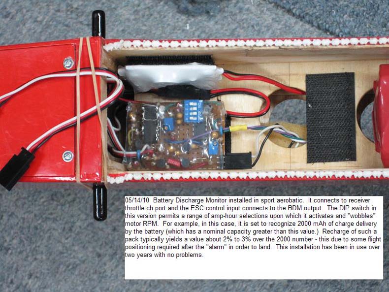
     Most of my active fleet is now outfitted with BDM's with more installations on the way. In the case of those planes that use the 2.2Ah packs, I have them set to "alert" at about 1.6Ah. The alert I use is a "wobbling motor RPM". (A friend has tried sounding a piezo beeper and / or flashing a very bright LED instead.) But why 1.6Ah for a 2.2Ah pack - isn't that a bit conservative?
     Yup - it is - sort of. Understand that the "alert" can occur during any flight aspect. The plane can be high or far, or in the middle of some aerobatic stream. Or, depending on the environmental noise level (there is still noisy wet power around!), one may not hear / recognize the "wobble" alert immediately. And following alert, it's necessary to get from that particular flight orientation / location into perhaps a go-round, then approach, landing, and taxi back. All these considerations take some small additional and variable Ah during which the motor is pulsing but still providing plenty of averaged power to get back home safely. So - for me the final drain on the pack is typically 2% to 5% more than the alert Ah value. This explains my conservative BDM setting.
     The "wobbling RPM" alert has never failed me in the nearly 3 years of use. Since a wobbling RPM is not conducive to continued "normal" flight behavior, it's pretty hard not the heed the call to land. In the overall of this, my packs typically finish up right around the recommended 20% charge remaining level - something routinely obvious from subsequent charger-reported ampere-hours. Incidentally, the BDM works with any cell count, does not make use of the pack balance connector, is plugged into the Rx to ESC path, and uses a very low value shunt in the battery to ESC path to capture "amperes with time" information.


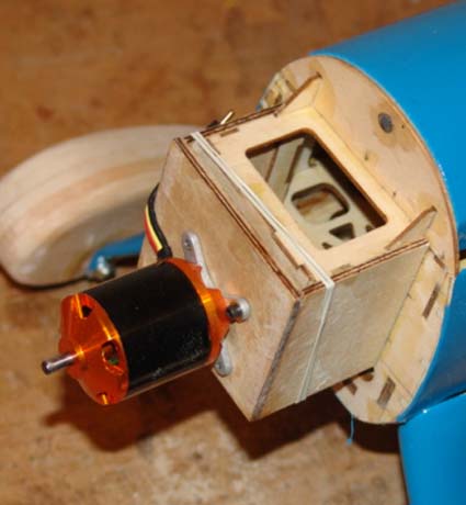
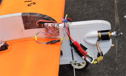
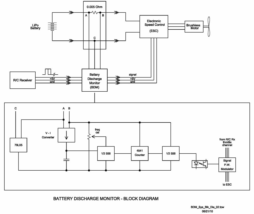
     I've included the block diagram of the BDM concept and some photos. Admittedly my assemblies are a bit crude - being built with analog technology on hole-board with discreet (leaded) components. I know the idea could be built much better / smaller with SMD techniques employing microprocessor control that would allow programmability for a wide range of "alert" value settings. Ultimately, I think the BDM idea would be best realized as a functional part of the ESC itself. This would result in the most compact / lightest installation overall and become just another easy ESC parameter to program. Now a brief "how it works" -
     Current out of the battery is sensed with the shunt resistor (I use 0.005 ohms) and the resulting voltage drop is routed to an op-amp / voltage-to-current converter circuit. This circuit outputs a much smaller, directly proportional current to charge a timing capacitor in an astable "555 timer" circuit. This results in a local clock frequency proportional to battery current - the more current the higher the clock rate. This varying astable output is then routed to a counter IC which, when the count is "full", outputs a gate signal. Thus, it takes both battery current and time (ampere-hours) to reach this point. The latter initiates another astable clock - this one a slow square wave of about 1 Hz. This signal in turn modulates the Rx to ESC control pulse width thereby varying the motor RPM.
     Summarizing, now after a few years of flying varied approaches to guarding Li-Poly batteries from over discharge (and sometimes failing!), I'm satisfied nothing is as effective as using coulomb count. It is in every way at least as good as the pack label capacity statement and has never failed me. For those who may like to experiment with the BDM idea/design, I can email some .pdf circuit details and you can give it a go. I do not have a step by step "how to build" document - you're on your own with this aspect, and so I'd recommend this for "more experienced and better equipped" experimenters. In any case, please feel free to let me or Ken Myers at the Ampeer in on your thoughts about, and reaction to, the BDM idea. And if you think it's a good idea, also go lean on some ESC manufacturers. But no matter what, as should be obvious, I'm sold on the Battery Discharge Monitor idea and I intend to keep using it!

Cordially,
Bob Kopski
K3NHI

Return to "What's In This Issue"

Complete coverage of the 2010 Mid-Am will be in the September 2010 Issue of the Ampeer


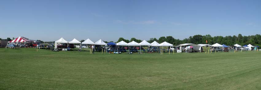
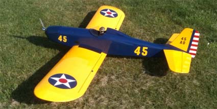
Saturday Morning at the Mid-Am


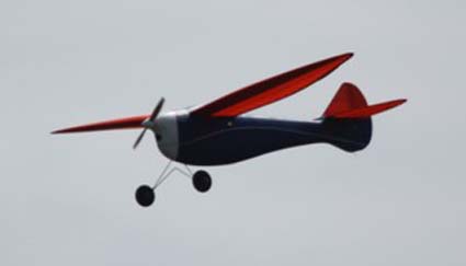
One of the great planes flying at the 2010 Mid-Am

Return to "What's In This Issue"

Comparing Glow Engines to Electric Power - Again
By Ken Myers

     There is really no good answer to the question "How does a glow 2-stroke or 4-stroke or even a gasoline engine compare to an electric power system?" The two types of power systems are completely different in how they "create/generate" a given plane's performance and the user's perception of that performance. For more information on this see "Part 2: How Electric Power Systems 'Create' Usable Power Compared to Glow and Gas engines" in the upcoming October 2010 Ampeer.
     Many folks have suggested that by using a 2-stroke's cubic inch (cu.in. or in3) displacement and a multiplier, the two very different types of power systems can be somewhat equated, if needed, like when converting a glow plane using the 2-stroke engine displacement recommended by the manufacturer. For typical sport 2-stroke glow engines the multiplier most frequently used is 1500 and for high performance 2-stroke glow engines the most frequent multiplier I've seen has been given as 2000.
     Until the July 2010 issue of Fly RC and the March 2010 issue of R/C Model Aeroplane, I had been unable to substantiate these rules of thumb with good, hard data. Most of the glow engine reviews, that I have had access to, use props that I do not have the prop constants for to find the approximate power out at a given RPM. The Fly RC Engine Review of the O.S. 46 LA, starting on page 36 and the R/C Model Aeroplane of the O.S. Max 95AX starting on page 117, solved that problem, as I had the constants for several of the props that Andrew Coholic and Brian Winch used to test the 2-stroke engines.
     Table 1 demonstrates the multipliers with cubic inch displacement in the left column, sport engine equivalent watts in occupying the center column and equivalent watts in for performance 2-strokes in the right column.


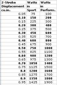
Table 1: Conversion Table

The 46 LA as an Example

     According to the Conversion Table, an electric power system with about 675 watts in should be equivalent to a sport 0.46 cu.in. displacement engine, which this engine is, and about 900 watts in for a performance 0.46. If the electric power system has a system efficiency of 75%, not an uncommon system efficiency for this size system, then the power out in watts would be about 506 watts or about 0.68 horsepower (hp) for a sport engine and 675 watts or about 0.90 hp for a performance engine.
     Andrew chose to test the 46 LA engine with three differing amounts of nitro methane in the glow fuel - 5%, 10% and 15%. His results are listed in Table 2: Andrew's Data along with my determinations of pitch speed, approximate watts out, approximate hp out and watts in required for an electric power system that is 75% efficient.
     For test flying, Andrew used a Sig Four Star 40 ARF and chose 10% nitro fuel and the APC 11x5 sport prop. It is interesting to note that the 11x5 has the lowest horsepower output and pitch speed of the props in any given nitro percent group in the table. I'm not indicating that this was a poor choice, since deciding on a prop that flies the plane "best" is not just a result of the numbers, but what actually works best in practice. The Four Star 40 has a fairly large wing area for a "40" size plane and is somewhat heavier than some, so the choice of an 11" diameter prop seems to be a good one, but I do wonder why he didnŐt go with the 11x6?


Table 2: Andrew's Data

The O.S. 95AX as an Example

     According to the Conversion Table, an electric power system with about 1425 watts in should be equivalent to a sport 0.95 cu.in. displacement 2-stroke motor, and about 1900 watts in for a performance 0.95, which this engine is. With a 75% efficient electric power system, then the power out in watts would be about 1069 watts or about 1.43 horsepower (hp) for a sport engine and 1425 watts or about 1.91 hp for a performance engine.
     Brian used a 10% nitro fuel for his test of the O.S. Max 95AX. Here are his results along with my determinations of pitch speed, approximate watts out, approximate hp out and watts in required for an electric power system that is 75% efficient.

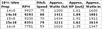
     The data illustrates that the 'rule of thumb' is quite reasonable. The 'rule of thumb' for the sport 46 LA suggests 0.46 * 1500 equals 690 watts in, and that certainly puts the user of the rule in the ballpark. The performance 95AX is 0.95 * 2000 = 1900 watts in. Again, the data confirms the 'rule of thumb'.

How about the inverse; electric to glow 2-stroke?

     Sometimes glow fliers ask electric fliers what their electric power system is equivalent to in the glow 2-stroke world. You can use the table that shows the 2-stroke to electric equivalents in reverse, or simply use the multipliers as divisors.
     My Super Stearman uses a power system that shows 435 watts in on my Emeter II. An equivalent sport 2-stroke would be 435 / 1500 = 0.29 cu.in. and a performance 2-stroke equivalent would have a displacement of 435 / 2000 = 0.22 cu.in. Using those numbers or the numbers from the Conversion Table, I could tell the glow flier that my power system is about the same as a "25" 2-stroke.
     Let's take this all a step farther, although now would be a good time to reread the first paragraph.
     How would my Super Stearman fly with a sport Enya .29 mounted in it? I don't think I'd care for it. The Enya .29, while creating about the same power out as my electric system, could only use a 9" or, at the very most, a 10" diameter prop. My electric system uses a 13x8 prop. When using the Enya 2-stroke the thrust would be down quite a bit and the pitch speed up, neither of which would suit the Super Stearman airframe or its flight mission well.

The 4-stroke Glow Engine

     Using another 'rule of thumb', to find the 4-stroke glow equivalent to a 2-stroke glow engine, multiply the 2-stroke displacement by 1.5. The multiplier of 1.5 comes from the old AMA rules when 2-stroke engine size was specified for an event and someone chose to use a 4-stroke. Today's 4-strokes are more powerful, so the resulting multiplier would be smaller, but for our purposes it will do just fine. A 0.29 cu.in. displacement 2-stroke, like the sport Enya "29", times 1.5 is equivalent to a 0.435 cu.in. 4-stroke. That is right between a 40 and 45/46 4-stroke. An O.S. FS-40 Surpass 4-stroke can swing up to a 12x6 prop, according to the data on Tower Hobbies Web site. When going glow 4-stroke on the Super Stearman that could be a usable choice.

Even Easier Glow to Electric Conversions

     The previous example demonstrates how 4-stroke engines are more closely akin to electric power systems in how they "create" a given plane's performance and the user's perception of that performance. It also illustrates the relationship of a 4-stroke glow engine to the power in of an electric power system. Did you see the relationship?
     How many watts in is the electric power system in my Super Stearman? What was the calculated displacement of the equivalent 4-stroke? That's right 435 watts in and 0.435 cu.in. displacement for the 4-stroke. The relationship works out so that dividing the watts in of an electric power system by 1000 yields the cu.in. displacement of a 4-stroke. To find the required watts in from a known displacement 4-stroke glow engine, just multiply the cu.in. displacement by 1000. The quick way to multiply by 1000 is to move the decimal point three places to the right. That doesn't require huge math skills. Another way to think of it is to drop the decimal point and add a zero to the right side.

Predicted Examples

     Here are a few predicted examples of some classic, and not so classic glow planes, that might be converted to an electric power system using the multiply by 1000 rule of thumb for 4-stroke engines:

Sig Astro Hog 4-stroke recommendation .60 to .80 equivalent to 600 watts in to 800 watts in
Sig Kadet Senior 4-stroke recommendation .35 to .45 equivalent to 350 watts in to 450 watts in
Great Planes Goldberg Eagle 2 Trainer 4-stroke recommendation .46 to .50 equivalent to 460 watts in to 500 watts in
Great Planes Goldberg Tiger 60 Sport 4-stroke recommendation .65 to .80 equivalent to 650 watts in to 800 watts in
Seagull/Horizon Hobby Spacewalker II 40 ARF by Seagull 4-stroke recommendation .40 to .82 equivalent to 400 watts in to 820 watts in
Hangar 9 Pulse XT 40 ARF 4-stroke recommendation .56 to .82 equivalent to 560 watts in to 820 watts in

     While all of the example planes would probably "fly" with the lower of the two watts in numbers, I believe that most modelers would be happier with the results obtained by using the higher of the watts in numbers.

Some Specific Examples of Actual 4-stroke Conversions

     Rich Sievert of the Midwest RC Society has had an Astro Hog for many, many years now. It has well over 500 flights on it. He actually logs every flight. He converted it to electric power and the most recent 33 flights have been with the electric power system. It is a true conversion spending its early life with various internal combustion engines powering it.
     The electric power system uses a 9S1P "A123" 2300mAh pack, Scorpion S-4025-16 and an APC 15x8E prop. The system pulls just over 35 amps from the 9S pack for about 925 watts in while turn the 15x8E at about 7500 RPM. The theoretical pitch speed is approximately 56.8 mph and thrust about 155 oz. or 9.7 lb. His eight pound plane flies great and he loves electric power now and thinks this is the best all-a-round power system he's ever had in it. This clearly demonstrates that power and performance are closely tied in with the pilotŐs perception.
     Based on my statements, he's using the equivalent of a '90-ish' 4-stroke, but swinging a larger prop for more thrust than a typical '90-ish' 4-stroke. His last 4-stroke was a Saito .82.

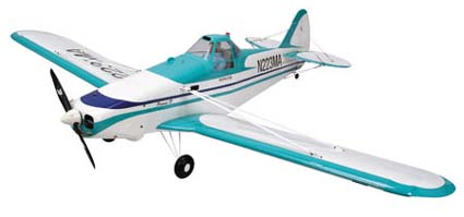
     The March 2010 issue of R/C Model Aeroplane has a review of the Hangar 9 Piper Pawnee 40 ARF crop duster by David Ashby. (starting on p.14) David chose to power it with the recommended E-flite Power 46 outrunner, Castle Creations 60 amp ESC and a 4S 3700mAh Li-Poly battery turning some type of 14x6 prop. He states that the watts in for his 8 lb. model is approximately 700 at about 46 amps. 700 watts in, based on my statements, suggests a .70 cu.in. 4-stroke or .46 cu.in. 2-stroke.
     Horizon Hobby recommends a .46-.52 2-stroke or .62-.82 4-stroke.

Summary

     To select a power system for a glow conversion, use the manufacturer's recommended 4-stroke displacement, drop the decimal point and add a zero to the right. If the manufacturer does not give a 4-stroke recommendation, multiply the 2-stroke recommendation by 1.5, drop the decimal point and add a zero to the right. Those numbers represent the approximate watts in for somewhat equivalent power.

Return to "What's In This Issue"

Stinson SR-10 Modifications to SR-7/8
From Gary Gullikson ggullikson@socal.rr.com


Pat Trittle photo of his prototype SR-10

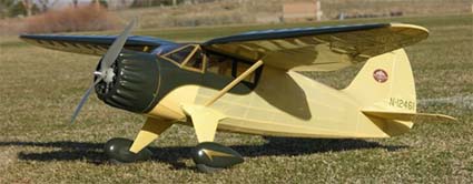
Hi Ken,

     I've been following your PT-17 conversion, looks great. I am currently building Pat Tritles's recent Stinson SR-10 Reliant short kit and have a build thread going in E-Zone Scale Electric Plane forum.

www.rcgroups.com/forums/showthread.php?t=1236193

     I will modify the forward cabin/windshield structure to the SR-7/8 version and will add a number of scale cabin details including gray poster board paneling, seats, instrument panel; 3-spoke "steering wheels" and a pilot thrown in for good measure. The model will weigh about 32 ounces, wingspan is around 58 inches, has flaps, requires six small servos and a switching type BEC. This will be my first model with flaps.
     The short kit costs around $107 from Pat's Custom Models. I will try my Scorpion 2215-22 outrunner and a 2200mAh 3S Li-poly for power. Pat used a Thunder Tiger .10 outrunner on 2S Li-poly and said that it was way too powerful.
     Covering will be light weight iron-on and Callie Graphics opaque vinyl stick on for two-tone scheme. There are a lot of Reliant lovers out there, so I thought you might mention Pat's new short kit in the Ampeer. The picture is Pat's prototype SR-10. I'm not nuts about the color scheme. He says the thing flies very scale like, not a floater.

Gary Gullikson

Return to "What's In This Issue"

To Reach Ken Myers, you can land mail to the address at the top of the page. My E-mail address is: KMyersEFO@theampeer.org
EFO WEBsite