|
Important Notice!
You can contact Bob Kopski regarding the BDM information in the October Ampeer at kopskib@gmail.com. I would appreciate a CC when you do - Ken
Bob Kopski BDM .pdf Link Corrections
Several readers wrote to let me know that the URLs to Bob's diagrams for the BDM were incorrect. I fixed them in both issues of the November Ampeer and reposted the issues. Here are the correct URLs for those of you still trying to get them.
www.theampeer.org/ampeer/ampnov10/BDM_9_Brd1.pdf
www.theampeer.org/ampeer/ampnov10/BDM_9_Brd1.pdf
Return to "What's In This Issue"
EFO Meeting Day Changed
Many folks noted that they liked not having the winter, indoor meetings on the Thursday following the Midwest meeting on the first Wednesday of the month. I've scheduled the December meeting for the second Wednesday of the month, December 8. Hope this works out for you all. See you at my house at 7:30, Wed., Dec. 8 - Ken
Return to "What's In This Issue"
Skymasters' Indoor Flying Special Day!
Last month I noted that indoor flying started on November 9 at the Ultimate Soccer Arenas in Pontiac, MI. The usual flying times are on Tuesdays from 11 a.m. to 1 p.m. There are more details at www.skymasters.org
There is a special flying day coming up. It is Friday, November 26. It is the Thanksgiving Weekend Indoor Flying Meeting at the Ultimate Soccer Arena, 867 South Blvd, Pontiac, MI from 2:00 p.m. to 6 p.m. It is just Just $15 for 4 hours of flying! As always, spectators are welcome and there is no charge for spectators.
Skymasters' event flyer is here:
www.skymasters.org/events/flyers/thanksgivingindoor.gif
Return to "What's In This Issue"
A Charger Voltage Test
From Dave Thacker of Radical RC
www.radicalrc.com
In the October 2010 Ampeer article "A Strange 'A123' 2300mAh Occurrence" Ken Myers notes that he found a 6S "A123" 2300mAh pack over 26 volts and wonders how it could have occurred.
I would submit there is no known way for an A123 battery to charge itself.
If we accept that it was only in the owner's custody during the time period, he must have charged it to or above the found voltage. It's certainly not impossible that an error was made either by the user or a charger. To accept any other possibility would be to infer he has a self-charging battery.
Arthur Conan Doyle: "Once you eliminate the impossible, whatever remains, no matter how improbable, must be the truth."
The October story made me think of another issue that comes up in the shop from time to time. I put to your readers to consider this question. We all have chargers. Most of these chargers will have a digital screen with a voltage read out. When you're charging (or discharging) your favorite battery, where is the voltage being measured?
It's an interesting question and I've found hardly anybody who knows or understands the answer. It's really very simple though not straightforward. What is your answer? I submit to you that your charger does not display the voltage of your battery. There really is a simple point of logic here. Certainly nearly everyone reading this will look back on their experience charging batteries and think to themselves that I've gone nuts. But, I submit to you that I have not, and if you'll participate in a little test you will soon be a "crazy" like me.
Let's gather the parts of our test. We need a charger with a digital readout that accepts banana ended charge cords. To make this test simpler, let's use a Li-poly or "A123" pack. I want you to use one of these kinds of battery packs because it has multiple connections to the cells inside and will make the test easier than if we use a NiCad or NiMH pack. We will also need a digital voltmeter with probes.
We can do this test under charge or discharge, you decide. I want you to apply a 2-amp charge or discharge load to the pack. If it's full, you'll be discharging, if it's empty, you'll be charging. Charging or discharging makes no difference. The results will be madness, I promise.
First, let's take a resting no-loaded volt reading of the pack. Measure the voltage out of the output wires (what you'd be connecting to your speed control) first. Jot down this number. Now, measure it from the red and black (or outer most 2 wires on the balance plug). Jot this number down. These two numbers should be identical.
Next, plug a charge cord into your charger and then into the output plug of the pack. If your charger is on, you should be able to read out the voltage on its screen and it should agree very closely with your digital voltmeter measurement. Jot this number down. There may be a slight difference here and we can explain that because the there may be some calibration difference between your meter and the charger. Also, most chargers do not read out to 1/1000th of a volt like your meter may read. Some chargers drop the digit, some round it. It's hard to figure out what your charger does here but let me promise you this. For the purpose of this test it is of no consequence.
Next it's time another measurement. Slightly pull out the banana ends of your charge cord from the charger so you can easily probe them with your meter. Take a measurement at the partially retracted banana plugs. Now, you have made 4 measurements and jotted down each of them. All are essentially the same voltage.
Now, apply your charge or discharge current of 2 amps to the pack. Connect your meter to the balance port of the battery. If your charging, you will see the voltage is lower in the battery (measured from the balance port) than on the chargers digital readout. If your discharging, you'll see the voltage is lower on the chargers readout than at the balance port. How can this be? Are they are connected to the same thing?
Another test is to move the meter back and forth between the balance port and the partially retracted banana plugs. You'll get a similar spread in your readings when you do this (while the pack is being charged/discharged). How can it be that essentially at both ends of the same connections you get two different readings?
If you repeat this test with a smaller weight charge cord, you'll get an even bigger disparity between the charger and voltmeter. Poor quality connectors (like Kyosho/Tamiya/BEC/etc) will add to the voltage difference as well. We've performed this test in shop and seen several volts difference before. What you are seeing is the voltage drop across the wires/connectors/solder joints, etc. between the charger and the battery pack.
Now that you've run the tests, you've seen the voltage in the balance port is not the same as the voltage at the charger. What I'm pointing out here is the simple logic of understanding that the charger can only measure the voltage on its circuit board where the banana sockets are soldered on. It's not measuring the pack voltage but the voltage as delivered by your connections to its internal circuit board.
Repeating the test at lower charge/discharge rates will show lower differences in voltage readings. Higher discharge rates will produce higher differences.
Higher resistance charge cords and connectors cause all kinds of problems. The higher the resistance, the more of your capacity is being wasted making heat (warming up the wires and connectors) rather than spinning your prop or being measured when you test capacity. The lighter the wire or more worn (or poor quality) the connections between the charger and the battery, the less accurately it can do its job and the less accurate the information it will provide you.
I've had instances of customers replacing battery packs with new ones which they tested to be just as bad as the ones they replaced because the charge cord was faulty or too cheaply made. The discarded packs were good when tested with a better quality cord and/or connectors. I've even had a customer with a 50cc gas model lose it in a dead-pack crash because he was using a "Quick" charge mode on an "A123" pack. In this mode the charger pumps the pack up to 80% where it's safe to fly again. He flew and crashed because the resistance between the charger and the charged pack was so high that the charger was reading out a couple volts higher than the pack really was under the condition of being charged. This condition was aggravated due to the high charge rate and small charge cord size. After the crash the pack was empty yet cycled good.
The point I'm trying to drive home here is don't assume anything. There are many facets to doing accurate charging and battery testing that is overlooked by most. Certainly this short article will have confused some and enlightened others. One could go on to explain Ohm's law and use these test measurements to calculate the resistance of your charging harness and thereby infer the error (believe me there is one) in your discharge readings when testing battery packs. But, I don't think we need to take it that far in order to get the idea across. Are you crazy like a fox yet?
Dave Thacker, Owner RadicalRC.com
Radical RC
www.radicalrc.com
5339 Huberville Ave
Dayton, OH 45431-1250
#937-256-7727 Voice
Email/PayPal: davthacker@aol.com
Where the excitement is building!
Return to "What's In This Issue"
Cloud 9's RC Micro World e-zine now FREE
I'm passing on some information I just recently received from Bob Aberle. Here is a quote from Roland Friestad, Editor of RC Micro World, "RCMW has always been a subscription based on-line magazine and will continue to be, but with one major difference. Now anyone can read each issue whether a subscriber or not. Well, you say, why should I subscribe then? Good question and here's the answer. Only paid-up subscribers can download the full size plans, 3-views and other special projects that are in every issue. Every issue contains at least one new model plan or 3-view scaled to the proper size for Micro RC. Most issues have multiple plans and 3-views. You can read the latest issue by clicking on this link."
The link for this month's issue can be found at www.co-op-plans.info/rcmw/rcmw%20visitor.pdf
Return to "What's In This Issue"
A New PT-19 for Rick
From Rick Sawicki rrrjjjsss@aol.com
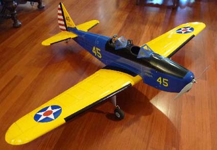
The PT-19 had always been one of my favorites ever since I went for a one hour, full acrobatic flight back in 1969. It was a reward for winning Hi-point in control line at the Canadian Nationals that year.
The specifications on this plane are; it is an ARF from Nitro models with a 63-inch span and 612 sq.in. of wing area. It has a ready to fly weight of 5.5 lb. with 4-cell 3700mAh Li-Poly battery.
Return to "What's In This Issue"
More on the Problem with CellPro 10S Adapters from FMAdirect
From Jim Cross, via email
Hi Ken,
Thank you for yet another excellent issue of the Ampeer. I always enjoy reading them.
In regard to Joe Hass's problem (in the October 2010 issue), I have an alternate theory on what may have precipitated the problem. As a former designer of wire harnesses and wire routing inside business machines I'm familiar with the "cold flow" property of the thermoplastics used to insulate circuit conductors. Over time, many thermoplastics will "cold flow" away from any pressure point on that material eventually exposing the conductor beneath. This is likely to occur where the material is pinched, drawn snug around a sharp corner or over top of a sharp point (which concentrates any pressure over a miniscule area). Careful close inspection should reveal whether the insulation around the bared conductor has thinned from "cold flow" or whether there was an actual puncture.
Best Wishes,
Jim
and
From Richard Driftmyer, via email
Ken,
I was looking at the October issue and noticed the article on FMA adapter boards. I've had 2 of them do this but didn�t realize what was causing this. I had the same result with FMA as the writer did. Not happy.
Thanks,
Richard Driftmyer
From John Zook, via email
Hi Ken,
Just finished reading the article sent in to you from Joe Hass concerning the charge adapter boards used by FMAdirect. I too have noticed a solder point protruding through the heat shrink. Not very far but could be far enough to short the charging circuit while in operation. Fortunately I normally charge my packs on a ceramic surface, but in the past, at our club's flying field, the charger was placed on a metal shelving unit. I should consider myself lucky that the adapter did not short out my Cellpro 10.
Another way to insulate the bottom of the adapter boards is to use some sticky backed foam used for insulation between gaps in doors. Most of us probably have some sticking around somewhere (pardon my pun) and as long as it's somewhat similar to a closed cell type foam should work nicely.
I checked another adapter board that I bought with my Cellpro 4 and it does have a dense foam layer on the bottom of the board. So there's your answer. At some time FMA was aware that the possibility of a short due to the solder joints breaking through the heat shrink could happen, but why did they not take the same precaution with the boards used with the Cellpro 10?
Right now I'm charging up a slew of packs for tomorrow's flying session using both the Cellpro 4 and 10 and the power supply is definitely working tonight. I also use the computer to monitor each session and twice during the season I also monitor the internal resistance of the packs. This is one of the features that drew me to the Cellpro 10.
All in all the unit has worked quite well, however, it does need to go into FMA for readjustment as it tends to charge the #2 pack to 100% and leaves the #1 pack a little low when it shuts down. I emailed FMA and received a reply from Howard Matos about the problem. Since I'm having no real problem as I can just leave the #1 pack connected and cycle through the charge until it reaches full capacity. I will of course send it in this winter when the weather shuts down flying for a bit. I usually wait for the lake to freeze over and fly off the snow covered ice.
Also I have included a photo of a Mud Duck completed and flown by Jim Maine of Ellsworth, Mi. Power is a Scorpion SII-3026-890, 4S Li-poly pack through an APC 15x8E prop (I believe). The Scorpion provides more than enough power for this duck and Jim reports that it's one of his favorite planes.
Cheers from Up North,
John Zook

Jim's Mud Duck
I hope everyone has taken the precautions with these adapter boards by now. I don't want anyone to get the wrong impression. I LOVE my CellPro 10S and it is my go to charger all the time. I am only trying to make the readers of the Ampeer aware of the possible problem and the simple fix. Ken
Return to "What's In This Issue"
A Polaris Takes Float
From Denny Sumner via email

Ken,
Here is a picture of my Polaris actually on water!
We had a good time on Lake Leelanau and I got a number of flights off the lake in glassy conditions. We also had a 1:1 Piper Super Cub stop buy and it was giving rides...Heck yes!!
See you,
Denny
Return to "What's In This Issue"
Control Line EDF with Thrust Vectoring
From Rick Sawicki rrrjjjsss@aolcom
While it is not April, I thought that this not so tongue-in-cheek description of the Future Control Line Stunter would be fun to share with you all. If you are interested, for real, in control line flying using electric power, Rick is the guy to contact. He's been doing it for a long, long time now and can help point you in the right direction when using electric power to power a control line plane. Ken
Hi folks,
I thought I would give you a little entertainment and present to you my latest stunter. I will also be defining and showing some of the major features that it has which you will not find on today's "conventional", old age model. It's been fun thinking about the presentation and possibilities for the future.
Major features and rational
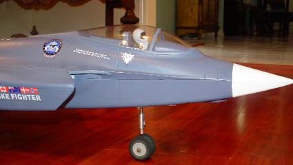
MINIMAL FRONTAL AREA resulting in less drag and more efficient MOTOR/BATTERY USAGE.
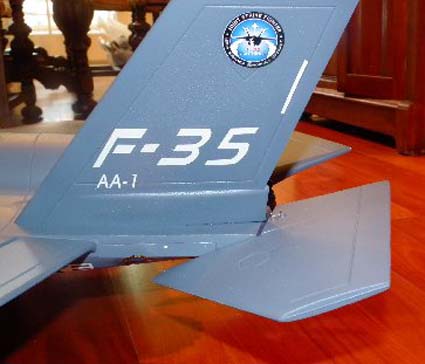
BIG STABS,IN FACT "FLYING STABS" with lots of movement.
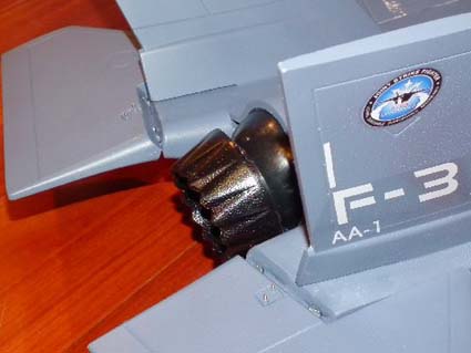
OK, now let's go for help in the corners by adding "VECTORED THRUST"!!! We'll also go for Max power using a 4-cell pack, of course, which will give us a POWER TO WEIGHT RATIO of over 2:1!!
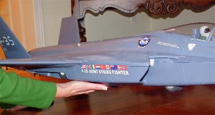
Now let's get rid of excess drag and add "RETRACKS". Note the GREAT COOLING ducts along side the fuselage for the battery and motor cooling.
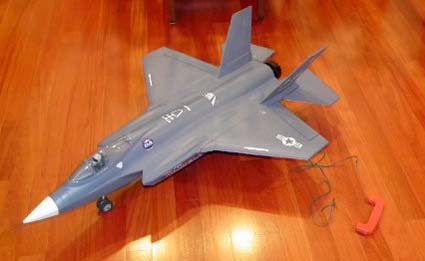
Now to prove it's a control liner, let's add the LINES AND HANDLE
That's it folks. Welcome to your first exposure to the "stunter of the future"!!!
It has a 31-inch wingspan and it is 47 inches long and 36 oz. ready to fly. While the span might be short, there is a 'TON' of body area to help the corners.
Being creative is a fun part of modeling, even if it is just mentally creative! This is what we do here in Michigan when you've got too much wind to fly for most of the summer. We get creative! Ken
Return to "What's In This Issue"
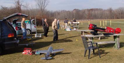
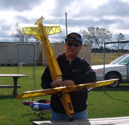
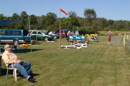
The November EFO Meeting

A pretty but cool day
The November flying meeting was held on Saturday, Nov. 13. It had been postponed from Nov. 6 because of the cold and rain on that day. The temperature was cool, but not too cold. The skies were clear and the sun was shining.

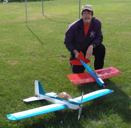
Jim and Tim Young Try Out a New 'Bird'
The turnout was very good for the EFO members, Midwest RC Society members and spectators.
Once again, Midwest RC Society president, Arthur Deane provided us with a hot meal of soup and hot dogs. Perfect field food for a day like this. Thanks Arthur for keeping us fed all summer!!!
There was a lot of flying throughout the day with many folks trying to get in as many flights as they could before we are weathered in.
 Return to "What's In This Issue"
The September EFO Flying Meeting

A Great Day for some Relaxed Flying
September was not a good month for RC flying in southeastern Michigan. The monthly meeting was put off until the last possible day, Saturday, September 25.
Rick Sawicki gets ready for a great day of flying

It takes a lot of planning to have a great day at the field.
It turned out to be a very good day for flying. It was cool, pleasant, somewhat cloudy, but mostly sunny.

The Master Chef, Mr. Arthur Deane
Arthur Deane set up the grill and fixed a great field meal. He cooked up a batch of hot dogs and it was an excellent field feast! Thanks again Arthur, mister master chef. It was great.

Chow Time!
There was a lot of flying before, and after the lunch break.
James really enjoys flying his Mountain Models planes.
The most exciting incident was the three-way mid-air during a session of combat. It was amazing. Dave and Paul got tangled up just after takeoff and then Rick, not knowing where they were, flew right into Dave's and Paul's planes which were entangled and spinning slowly to the ground. All three planes, or what was left of them, crashed safely on the far side of the runway. They were all very close to each other. What you see when you don't have a video camera running!
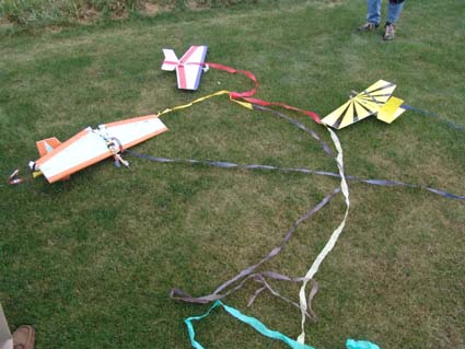
The crashsite
I've seen lots of mid-airs over the years, and have been involved in a few, but I've never seen a three-way. Amazing guys. Wanna try it again for the video?
Return to "What's In This Issue"
The August EFO Flying Meeting
Flying days in August were few and far between. The August meeting was postponed because of extreme heat and wind until August 27. As usual, we were running out of month before flying days showed up.

The turnout was great, and there were a lot of different types of aircraft at the field and in the air.
Finally, it was a beautiful day with light winds and warm temperatures.

Roger Wilfong debuted his new 4-Star 380. It is about the same size as the new Sig 4-Star 20 EP kit, but Roger's was scratch built while the kit was only a rumor at Sig.
Howard Shorr relaxes and watches a flight
Return to "What's In This Issue"
Our Second July EFO Flying Meeting

The Mid-America Electric flies are held on the weekend after the 4th of July, so we don't usually have a second flying meeting in July. We had perfect weather for the Mid-Am this year, and it was followed by a second weekend of decent weather on July 17th. The Mid-Am write-up and photos are in the September 2010 Ampeer.
www.theampeer.org/ampeer/ampsep10/ampsep10.htm
www.theampeer.org/ampeer/ampsep10/ampsep10.pdf

As usual, we had a great time with friends, flying and sharing 'war stories', most of which were probably not true.

Paul Sockow's 1/4-scale Clipped Wing Cub
Return to "What's In This Issue"
The New Solder - RoHS Solder (95% Tin)
By Tom Hunt
From the 2010 Nov. SEFLI Newsletter
With permission of the author
Many people have had problems recently, both in and out of this hobby, in regards to failed solder joints. Recently (2006) the EU and Asia have enacted "lead free" legislation for consumer electronics to reduce the amount of heavy metals disposed of yearly. Conventionally, electronics solder has been 63% tin and 37% lead known as eutectic solder. New RoHS (pronounced ro-hoss) solders are mostly Tin (over 95%). This changes the melting point from the mid 300 deg F to the Mid 400 deg F melting point. These 2 solders do not like mixing due to the differences in melting points. This can lead to a joint that appears to have good wetting, but the bond between them is actually a cold "reflow". This leads to a joint that fails under mechanical or thermal strain.
The best way to solve this problem is to remove all the RoHS compliant solder. The easiest way to do this on battery and ESC leads is by cutting back the pre tinned leads. On connectors and components, it is a little trickier. You have to wick it off. If you see a product with the RoHS verbiage or a compliancy statement, just keep it in mind.
Bob Aberle sent along this link where you can learn more about this type of solder.
www.hardwaresecrets.com/article/RoHS-Explained/232
Return to "What's In This Issue"
| 
