|
Flying High With Electric Power!
The Ampeer ON-LINE!
Fly the Future - Fly Electric! |
|---|
Site Table of Contents
| President: | Vice-President: | Secretary-Treasurer: |
| Ken Myers | Richard Utkan | Rick Sawicki |
| 1911 Bradshaw Ct. | 240 Cabinet | 5089 Ledgewood Ct. W. |
| Commerce Twp., MI 48390 | Milford, MI 48381 | Commerce Twp., MI 48382 |
| (248) 669-8124 | (248) 685-1705 | (2480 685-7056 |
 | ||
| Board of Directors: | Board of Directors: | Ampeer Editor |
| David Stacer | Arthur Deane | Ken Myers |
| 16575 Brooklane Blvd. | 21690 Bedford Dr. | 1911 Bradshaw Ct. |
| Northville, MI 48168 | Northville, MI 48167 | Commerce Twp., MI 48390 |
| (248) 924-2324 | (248) 348-2058 | (248) 669-8124 |
| EFO Meeting: Wednesday, Jan. 9 Time: 7:30 p.m.
Place: Ken Myers' house Everyone with an interest is WELCOME | ||
| More On the Introduction Glider Plenny Bates tells where to purchase it and offers to give some tips and pointers. | More On Setting Up Control Throws Andy Kunz enlightens us more on setting up control throws. |
| Indoor Flying Season, 2018-2019, Southeast Michigan Dates and times for the two venues in our area | Pack Test and Comparative IR Using Three IR Meters Ken Myers discusses the value of knowing the internal resistance of a battery pack's cells. |
| Fall Restoration Project, PT-3, and Other News Keith Shaw describes the restoration of his 1970's rubber powered free flight to today's RC and a sneak peek at an upcoming project. | A Thanks and Thanks for a GREAT Contribution to the AMA Museum Walt Thyng sends a along a thanks to the Ampeer readers and makes a great contribution to the AMA museum. |
| Question Regarding Flight Timing Larry Lisowski asks a question about timing. | Problems Setting Up an Electric Glider With a Retracting Power Pod Mark Couling askes a question about his glider and notes some solutions he's come up with. |
From Plenny Bates Via Email Plenty told us about his new glider in the December 2018 issue. He sent along another email to share where he purchased it. The place is Hoellein in Germany. The prices are with VAT and that will come off. We chose air shipping. As I remember, the cost was about US $57, but that was for one, to I guess, any number of kits. We ordered 7 kits and paid only $57 for all. We also bought some other things. Most bought the recommended Hacker motor, spinner, prop, middle part etc. I was going to use Dymond D60 servos but had Hyperion so used plastic geared ones for rudder and elevator and metal gears for flaps. I got the Introduction so as to have no ailerons. If you get the Inside you have 4 ailerons. We did only a very few changes in construction. If wanted I can elaborate on what we changed. If you are adding more than a few grams, you have not made an improvement. I think I may have added 5 grams. With the other changes (from the plans and instructions) I am sure that I took more than that out. If you have anyone interested have them email me. I have a few suggestions that they may want to act on before they buy. Plenny
More On Setting Up Control Throws
Hi Ken, I finally got around to reading the September (2018) issue, and would like to answer your question about the holes in servo arms and control horns. Rather than looking at the linear change, I suggest you consider the rotation in degrees and ratios. A servo will typically rotate 60 degrees for normal 100% travel (1100us to 1900us pulse range), or 90ˇ for 150% rotation (900us to 2100us). As you have shown, the holes in the output arm are often spaced the same for opposing arms, and about halfway between them for the alternate arms. This is not always the case, so one should take care to measure each side so he knows. A control horn for a surface similarly has multiple holes spaced about the same as they are on the servo side. The difference with a control horn is that the pivot point can be typically anywhere from the base of the control horn to the far side of the surface (or beyond, for flaps and special things like gear doors). For simplicity I will assume that you will pick a value ranging from 0 to let's say 1/4" (typical surface thickness) and that there is no geometric differential (the holes in the control horn lie on the perpendicular to the hinge point of rotation, and the output arm of the servo is likewise perpendicular to the line of travel at center). For the sake of argument, I'll use 0 (meaning that the hinge is probably tape or covering and the control horn is on the same side). With that foundation understood, let's pick some numbers. I have a servo with holes centered at 8.5mm ("A") and 11.0mm ("B") on one arm, 8.0mm ("C") and 10.5mm ("D") on the opposing arm, and at 8mm ("E") and 11mm ("F") on the other two arms (this is a standard JR arm). My control horn has holes at 7.25mm ("a"), 10.35mm ("b""), 13.60mm ("c"), and 16.75mm ("d") (it's a DuBro #107). Now it's a simple matter to do the math to find the possible ratiometric options available to me with these two lever arms. Mixing and matching the letter combinations, we get A/a, A/b, A/c, A/d, B/a, B/b, B/c, B/d, and so on through F/d. Some of those combinations will be >1 (meaning you get more angular deflection than the servo) and some less (less surface rotation than servo rotation). The attached spreadsheet includes all that data for these two items. 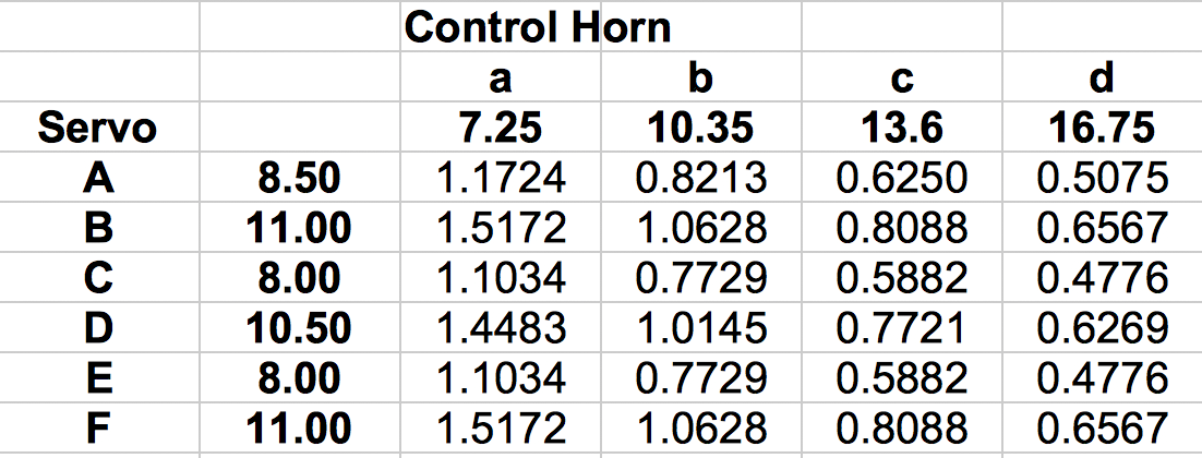 Since you know the rotation of the servo in degrees, and the rotation of the control surface (easy to calculate if you know the chord of the surface and the deflection in linear units), you can likewise do that math to find the ratio. Then you just look up the ratio in your table to find the pair that will give you the value most closely. At this point it's a good idea to inject some basic setup information:
Where this really comes in handy is with a carb, and that's probably why it wasn't so obvious to you as a long-time electric-only user. Carbs don't have many holes to pick from, and they have a pretty good amount of rotation, but fortunately most are not that critical about small differences. And you really want to be able to get the full range of travel to have both full power and engine kill. Andy Indoor Flying Season, 2018-2019, Southeast Michigan Tuesdays, October 30 through April 16, 10 a.m. - 1 p.m.
Ultimate Soccer Arenas
Single Flying Session - $10
All pilots MUST have proof of AMA Membership
Spectators Welcomed
Resister Online
Support your local hobby shop because they support us! Wednesdays, November 7 through April 24, 12:30 p.m. - 2:30 p.m. Legacy Center
Drop in Flying Session - $10 Spectators Welcomed and free There may be exceptions or changes around the holidays.
Return to "What's In This Issue" Pack Test and Comparative IR Using Three IR Meters
What's Up With All the Talk About a Battery's Internal Resistance (IR)? In his Electric column, in the December 2018 issue of Model Aviation, Greg Gimlick started his discussion of several ways to obtain a battery's calculated internal resistance. Part 2 will be in his column in the February 2019 issue. I also have discussed a battery's internal resistance, and how to measure it, in the September 2017 and October 2017 issues of the Ampeer. If you need more background, these articles should be helpful;
But why bother? What does this number suggest? Who cares? The internal resistance of the cells, resistance of their interconnects, resistance of the battery lead wire and connectors, as well the resistance of the wire lead length to the electronic speed control (ESC) determines the input voltage at the ESC. The final 'output' voltage, the RPM of the motor, is determined by the resistance losses in the ESC and motor, and the final 'output' voltage times the motor's Kv determines the RPM. The chosen prop determines the load seen by the circuit and measured in amps.
Example:
To keep the math as simple as possible, the numbers reflect only easily rounded values, not real world values. The resting voltage of the battery pack is 4.2V per cell and 3 cells are connected in series. The resultant voltage is 4.2V * 3 or 12.6V. If there were no losses, the 12.6V would 'enter' the ESC. The sum of the three cell individual measurements, for this example, is 24mOhm or 0.024Ohms. If the power meter noted the load as 10A, the voltage drop through just the three cells would be 0.024Ohms * 10A = 0.24V Using those numbers, the input voltage at the ESC would be 12.6V - 0.24V = 12.36V. The actual voltage shown by the power meter would be lower than 12.36V because of the rest of the resistances.
At a measured 20 Amp draw the voltage drop through the three cells would be 0.48V = 12.6V - 0.48V = 12.12V. At a 30 Amp draw voltage drop through the three cells would be 0.72V = 12.6V - 0.72V = 11.88V. If an actual reading, using a power meter, was made on that pack and it showed 12V and 10 amps under load, then; (12.6V - 12.0V) / 10A = 0.6V / 10A = 0.06 Ohms.
Something is out of whack here. 0.060 Ohms is 2.5 times higher than 0.024 Ohms. There are a myriad number of reasons the actual power meter numbers were so different from the predicted numbers based on the ohmic value. 1.) The cell interconnects, battery wires and connectors could have a much higher resistance than might be expected. That is not too likely, but could be possible.
For the sake of simplicity, we'll assume that points 1 - 3 are not true, because the load test was conducted at about the same ambient temperature as when the ohmic test was done, the pack was sized and has lead sizes appropriate for the load and the meters used have been calibrated to each other. A second device that yields ohmic values for cells could be used to 'retest' the pack. If the second device, used under the same conditions as the first's measurements, yielded a total IR for the three cells of 50mOhm or 0.05 Ohms. That value is a little over two times higher than the first.
The example's power meter's reading was 12V at 10 amps. There is only a 0.1V difference in what was predicted for the voltage and what was measured. It is obvious which device, or method, yielded the closer to real world results. I obtained three different total cell ohmic values, using the same battery tested under as close to identical conditions as possible, using three different devices to gather the values. To begin the real world testing, I reviewed the use of the meters by gathering the cell IRs using the three different devices. The pack was just up from the basement, where it was resting in its LiPo Sack. The basement temperature was ~15 deg. C or 59.2 deg. F. The resting pack's voltage from basement was 11.25V using a Fluke multi-meter to read the pack voltage. The Pack (known good): Dinogy Graphene 3S 1000mAh 70C
The following data was gathered:
Please keep in mind that these values are for a very cold LiPo pack. The pack was charged on a Revolectrix GT500 charger to 3.95V per cell and set by my plasma TV. My plasma keeps the ambient temperature around it at a fairly constant value. The pack was charged to only 3.95V per cell because ohmic value readings near 'full - 4.2V' and near 'empty' get a little 'whacky'. Yes, that is a scientific term. Before the ohmic values could be tested, the pack had to have time to stabilize its voltage. The following shows how long it took to stabilize. 30 minutes by Plasma TV
+15 minutes by Plasma TV
+15 minutes by Plasma TV
+15 minutes by Plasma TV
It took 1 hour and 15 minutes to stabilize. That is probably much longer than most of you would realize that it takes. The voltage and ohmic values for each cell were obtained. Revolectrix 'Honesty Meter' - 21.5 deg. C or 70.7 deg. F
The pack had to be stabilized again. +15 minutes by Plasma TV
+15 minutes by Plasma TV
It took 30 minutes to stabilize. Giles 21.2 deg. C or 70.2 deg. F
The results seemed quite similar to the 'Honesty Meter' with the Giles meter being only 1.09 times higher than 'Honesty Meter'. The pack was once again allowed to stabilize by the plasma TV. +15 minutes by Plasma TV
+15 minutes by Plasma TV
It took 30 minutes to stabilize. Finally the voltage and ohmic values for each cell were obtained using the Vollrath DIY meter. Vollrath 20.6 deg. C or 69.1 deg. F
The predicted voltage drop at 10 amps:
It would be hard to tell difference between the Revolectrix and Giles meters. +15 minutes by Plasma TV
+15 minutes by Plasma TV
It took 30 minutes to stabilize. Motor Test Using an Emeter II at 21.9 deg. C or 71.4 deg. F: The motor data was captured using 8 captures per second. The data was transferred to an Excel Spreadsheet named compare-tests.xls. I almost made a bad mistake but caught it. I almost forgot to let the pack stabilize before taking the final resting voltage reading. That is a very important number! After the first 30 minutes I took the battery voltage readings.
+15 minutes by Plasma TV
+15 minutes by Plasma TV
It took approximately 60 minutes to stabilize. The motor was on for 6.5 seconds. The highest values recorded were at 1.5 seconds into the motor run and were 11.26V and 9 amps. At throttle shutdown, the readings were 11.11V and 8.8 amps. The last reading is the MOST important reading, as the battery has completed 'running down' its voltage. The resting battery voltage at the beginning of the test was 11.77V. After stabilizing, after the test, the resting battery voltage was 11.73V at 21.2 deg. C or 70.2 deg. F. The no load voltage drop, because of the battery &auot;running down" is 11.77V - 11.73V = 0.04V. The Predicted Voltage Drop at 8.8 amps based on the Sum of the Cells Resistances:
Actual measured voltage drop under 8.8A load:
It is easy to see which device gave a closer prediction in this instance. It is also easy to understand how using a reasonably accurate ohmic value can help in determining what will happen in the real world. Remember the cells, and therefore the battery's, resistance is not a 'pure' resistance. The resistance changes with the temperature of the cells. It is really a moving target, yet it can still be a useful predictor of battery performance, as well as the relative health of the cells.
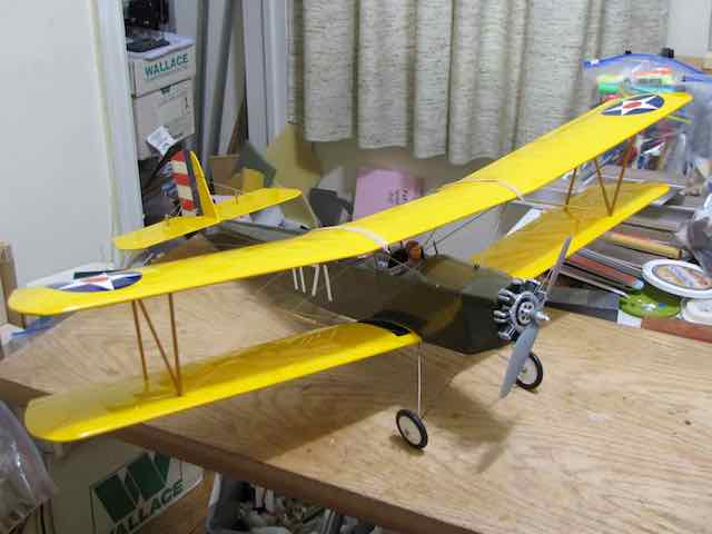
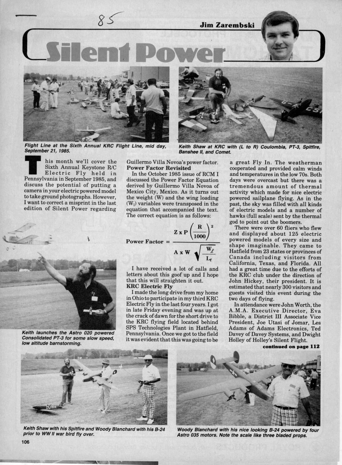
Fall Restoration Project, PT-3, and Other News
I just finished restoring my ANCIENT Consolidated PT-3. I had it at the 1985 KRC as there is a photo of me launching it (see above), but it was already old at that time.Ę I built it in November 1971 as a rubber model from the R/N kit that I won in a drawing. It is a 36" span model of an early US military biplane trainer. It has 360 sq.in. of wing area and weighed 6.5 oz. without the rubber motor. I had many wonderfully reliable flights on it before I ever moved to Ann Arbor. Somewhere in there the Telco CO2 motor appeared and I converted it for several more years of FF. About 1975 I handmade a tiny regen receiver and pulse rudder actuator powered by two N alkaline cells, but the extra weight reduced the climb on CO2 to just above zero, so after a few marginal flights it was converted to a PeeWee .020. However the plane was covered with Japanese tissue and nitrate dope, so I brushed on a thinned coat of HobbyPoxy clear paint for fuel proofing. About 1981 it was converted to electric (and RE control) with an Astro ferrite 02 and three 600mAh nicads and that is what flew with at the 1985 KRC. Needless to say the tissue eventually disintegrated and has hung on the wall in sad tatters. It was a ROYAL pain to try to get the tissue off as the epoxy clear would not allow any release thinners to penetrate, so I spent six tedious daysĘcarefully sanding the fragile structure. It has been recovered with ParkLite film and sports a 15gm out runner. 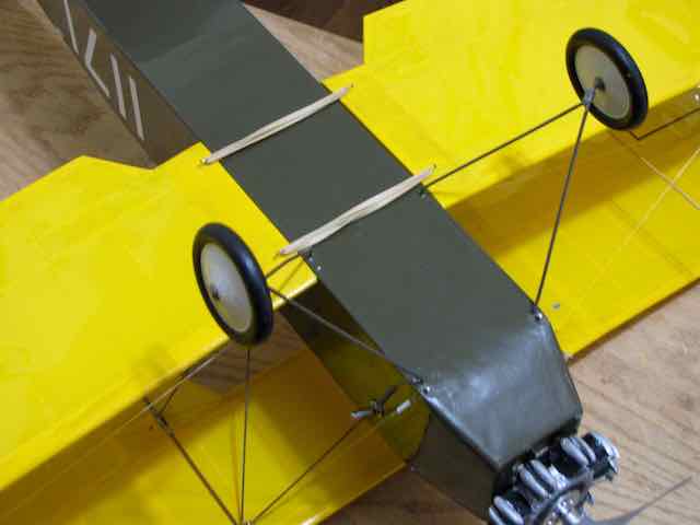 When it was flying with two s-22 servos, a stripped-down 2 channel receiver, a 100 mAh Rx pack, an Astro 02 and three nicads, it weighed a portly 19 oz., but now has slimmed down to 9 oz without battery. That's not bad considering the original FF was about 9 oz with the three (?) loops of 1/4" flat rubber motor! 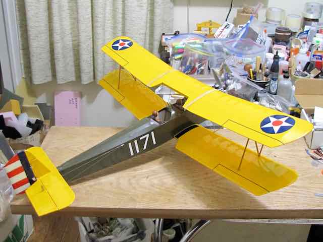 The previous heavy brushed motor and battery were far forward, so unfortunately with the modern light stuff in it it came out tail heavy. Instead of using a 400mAh 2S LiPo and having to add lead in the nose, I opted for two of the small 1100mAh A123 cells They weigh three ounces instead of one ounce, but have more than three times the usable capacity. The total weight is now 12 oz. I flew it yesterday (Nov. 25, 2018) after finally completing all the fall yard work. It just fluffs around with good agility and is much happier after the diet. I flew it for 15 minutes off the driveway at a local park and did about 20 touch-and-goes and even a couple of loops and stall turns. Recharging the pack put in 420mAh, so it could easily do half-hour flights. About the only change I made last night was to add a few degrees of down thrust, but probably won't be able to test it out until spring. I am working on one other small restoration project that should be done in a few days, then it will be time to start the drawings for this year's Toledo project.  I have decided to model Bill Barber's ultra-rare airshow Curtiss Falcon, as I have been given access to many photos of it from a mutual friend. The scale will be 1/5.5, giving 76" span with 800 sq.in. wing area and about a kilowatt power system. The Falcon is the only non-bred (not Extra, Cap, Suhkoi, Yak, etc.) plane I every saw do a vertical eight from the bottom and a vertical 4-point roll. 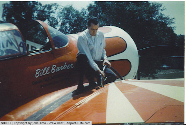 Keith A Thanks and Thanks for a GREAT Contribution to the AMA Museum
Thanks for posting my Puddle Master question in the Ampeer and more thanks to Joe Hass for the answer. An 05 on a PM?! Must be a rocket ship! 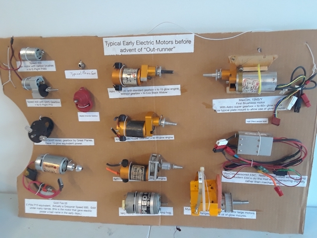 Ken, I put together the attached display of older motors for a "Retro Day" at our club (Fox Valley Aero Club). I was stunned at the lack of knowledge of the development of e-power so I decided to offer the display to the AMA. This link shows the result. Walt A Question Regarding Flight Timing
While Larry's question doesn't directly relate to electric flight, there could be some electric flight applications provided by the answer to his question. KM Hi Ken, I am a pylon racer and I am trying to come up with a consistent cadence device that I can use to prompt me when to turn around the pylon 1 on each lap. I have an iPhone and the voice record would be perfect if I could figure out how to activate it while I am flying. The problem is, the iPhone has a touch screen and you need to be looking at it in order to see the start button. I thought if I knew how the button on the touch screen worked I might be able to come up with a remote switch that I could attach to the back of the transmitter or even incorporate it into one of the toggle switches on the transmitter. I got your address from the Ampeer newsletter and although this is not on the subject of electric airplanes, I thought maybe with your experience you might have some ideas. This is the gist of my dilemma and I would be delighted if you could offer any suggestions. If you need more information and it would be easier to call, you can reach me at (708) 485-6749. Sincerely,
My Response: Hi Larry, I believe that I understand what you are trying to do with a timer/cadence. Interesting. ;-) I know what you mean about the iPhone and activating while while flying. Just a thought, but could you get Siri to start the recording? I'm going to post your question in the January 2019 Ampeer and see if some one has a good idea for you. Sincerely,
Problems Setting Up an Electric Glider With a Retracting Power Pod
Mark's questions are in normal font and my responses are in italics. Ken Picking your brain. I have a 2m motor glider (st-altos) no issues under power, climbs well and flies well at reduced power. But cut the power, motor retracts and it does a super hard stall (always) to the left (harder than any available stick input - like it hit a flagpole at the LH wing/fuse joint) dives vertically (that is the result of the stall - that that stallith fallith), and eventually, after about 30 feet drop, you can pull out and it flies good enough as a glider. The plane is well balanced for gliding and a little nose heavy with the motor in the active position. Seems to me that is should be more nose heavy with the motor extended. I'd shift or add more weight forward and see what happens. KM Given the above can you offer me any guidance? Landings often get a "fail" and soaring is hard because I lose so much altitude at the transition! Any thoughts or pointers? How is it that the landings are failing?
Is it possible that the wing needs to move much faster through the air to generate enough lift but the prop is adding enough lift to hold the plane in the air (as opposed to generating lift from the wing - harrier style). Ie the thrust line of the prop has become out of alignment with the thrust line of the plane? So when I drop the prop it immediately stalls to gain speed and the torque of the motor flips it hard left? How does the plane glide with the motor retracted from a hand launch. Find some tall grass to glide into. Turn on the radio system. Give the plane a good heave towards the horizon, not up, and carefully watch the glide. If its nose wants to rise, it is tail heavy. With a glider type plane, you should be able to get a fairly long glide and be able to see what is going on. KM I rebuilt it during the week and tested it yesterday and again today. During the rebuild I noticed that the thrust line of motor and wing were about 5 degrees divergent, ok, gotta push stick forward to climb controllably when the motor runs. However, I also noticed that the stabilizer stationary surface was negative 5 degrees to the wing line Ęso I put a 2 mm washer in on the front screw of the stab mount to get it parallel to the wing line and, when I flew it, it really improved both the glide and transition. Picture shows all the lines reflected on to the vertical tail surface using a laser level. One 2mm washer, huge improvement in flight!! 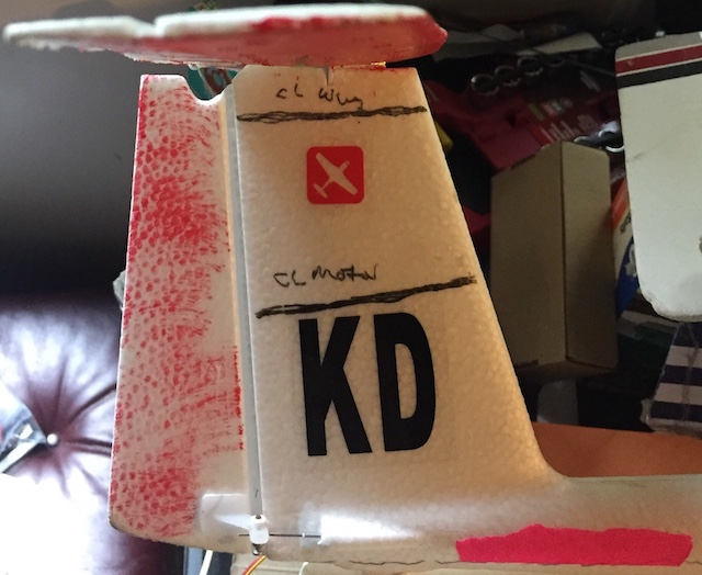
Photo of Mark Couling's tail on his glider with angles noted. Thanks for being a sounding board! To Reach Ken Myers, you can land mail to the address at the top of the page. My E-mail address is: KMyersEFO@theampeer.org |