|
Flying High With Electric Power!
The Ampeer ON-LINE!
Fly the Future - Fly Electric! |
|---|
Site Table of Contents
| President: | Vice-President: | Secretary-Treasurer: |
| Ken Myers | Richard Utkan | Rick Sawicki |
| 1911 Bradshaw Ct. | 240 Cabinet | 5089 Ledgewood Ct. W. |
| Commerce Twp., MI 48390 | Milford, MI 48381 | Commerce Twp., MI 48382 |
| (248) 669-8124 | (248) 685-1705 | (248) 685-7056 |
 | ||
| Board of Directors: | Board of Directors: | Ampeer Editor |
| David Stacer | Arthur Deane | Ken Myers |
| 16575 Brookland Blvd. | 21690 Bedford Dr. | 1911 Bradshaw Ct. |
| Northville, MI 48167 | Northville, MI 48167 | Commerce Twp., MI 48390 |
| (248)924-2324 | (248)348-2058 | (248) 669-8124 |
| Mailed Ampeer printed subscriptions are no longer available.
The Ampeer is FREE on-line in Acrobat .pdf format and HTML with active links! | ||
| The Next Meeting:
Date: Thursday, March 20 Time: 7:30 p.m.
Place: Ken Myers' house | ||
| More on Servo Sizing, Keith Shaw shares information on servo sizes he's used. | Control Surface Weight and Servos Steve Ralph shares an observation regarding the weight of the moving surface and servos. |
| Finding Required Servo Torque Using a Nomogram/Nomograph Plenny Bates describes how to use a nomograph to calculate required servo torque. | Measuring Maximum Servo Torque Ken explains how to measure servo torque. |
| the Min-E Mambo Ken shares his e-conversion of a 1963 Minnie Mambo. | New Tactic TTX850 On the Way Updated Hobbico information on the Tactic TTX850. |
| The February 2014 EFO Meeting The February EFO meeting featuring Roger Wilfong's Flying Flea, Denny Sumner's 1911 Caudron Racer, Arthur Deane's Blinker & Ken Myers Min-E Mambo. | Brighton Indoor Flying Date & Time Change Indoor flying now on Thursday's from 11 a.m. to 1 p.m.. |
| New Safety Rules Applied to Indoor Flying at the Ultimate Soccer Arenas Peter Foss explains the new safety rules and why they will be enforced. | Grob With a New Wing Paulo "Chispas" Faustino shares info on his updated wing and comments on indoor flying. |
| OSG Glider with a V-tail Owen Morgan shares the details of his v-tailed One Sheet Glider. |
From Keith Shaw, via email Hi Ken, Read your recent servo discussion and thought I'd throw in a few data points, some for grins and a few for :-O. Almost all my big electric scale planes use the Airtronics 102, rated at 50 oz-in. ĘAll of these use one aileron servo with bellcranks, so the servo only sees the NET load, plus a bit for linkage friction. CzechMate, 10 lb., 31% (elevator and aileron BB conversion)
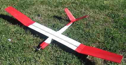
Possibly the "scariest" was the first two or three setups in my 1/4-scale Great Lakes (80" span, about 2000 squares if I remember correctly), built in 1966. This was when it was in factory configuration (2 ailerons and inline 4 cylinder engine), before I did the red&white Hal Krier conversion with decreased dihedral, four ailerons and radial engine. Ailerons were via bellcrank, but the rudder and elevator were cable drive, with internal counterbalances to cancel out control surface mass. It originally flew with my homemade digital servos that, while huge, were only about 15 oz-in torque (my guess). Later it was flown with Kraft-10s, Kraft-12s, and even the little red EK servos, all with torques optimistically in the 15 oz-in range. The Great Lakes at that time weighed 12 lb., and was powered by a twin-plug Merco 61 or an early Webra 61 grey-head. I mostly just flew around or did touch&goes, but occasionally would do a mild loop, roll, stall turn or spin. So... early Great Lakes, #12, 8% !!!! :-O When it was converted to the Krier version, it had Kraft-15s and later Kraft-20s, while the engines went from a OS Max 80 to a Quadra, Tartan, and finally a ST2500, while the weight peaked at 17 lb. BTW, the plane was fitted with full functional steel strip rigging. Those servos were about 50 oz-in, so the later Great Lakes, at 17 lb., for 18% was a little better. :-) I would shudder to think the surface power/weight ratio on planes I flew with escapements, pulse rudder and Galloping Ghost! Or my very first R/C plane in 1957 that weighed about 6 lb. and was laughingly "controlled" by a small rudder tab whose position was changed by two small relays. At best I would estimate an ounce of push on the rudder tab, with a 1" horn, so the equivalent of 1 oz/in of torque. A whopping 1% of the aircraft weight!!!!!! Thanks for inspiring this random trip down memory lane. Keith From Steve Ralph via email Tasmania I had never heard of this before and wonder if any Ampeer readers may have noticed it. KM Ken, I just picked up the article in December 2013 Ampeer, as I was looking for a servo size guide. One thing you failed to cover was control surface weight. I've found small servos often lose gear teeth in a hard landing with balsa control surfaces. The same size servos in foamies, with similar size (not weight ) surfaces, last a lot longer. Thanks for the info in article,
From Plenny Bates via email Plenny provided me with some information about using a Nomogram/Nomograph to calculate the required servo torque. A nomogram, also called a nomograph, is a graphical calculating device to allow the approximate computation of a value graphically. For some people, it is easier to use than mathematical formulas. The nomograph Plenny was referring to came from the August 1998 RC Model World. It was created by Alasdair Sutherland in October of 1997 and appeared in his column "aerodynamic forum". The nomograph is based on the work of Carl Risteen. Carl's article appeared in Model Airplane News in the Autumn of 1993. Sorry, I could not find the exact date. Plenny sent along a few cautions and observations about using the nomogram. Ken, All the calculations are done by the nomogram. You can see surface span is linear but the chord is squared, as is the airspeed. The author cautions that you must use most of the travel of the servo. I will add that one should assume published specifications for a servo may be generous and one must allow for hinge and pushrod drag. A couple of caveats on the use of the nomogram. The numbers you get seem to be the absolute low number if everything is right. Several factors run up what you really need. Drag of the linkage, not using the full travel of servo, errors in your input ( speed etc) and unsaid, but the data from the manufacturer may be on the optimistic side. Also you must consider something that has nothing to do with the power needed. You must ask, "Is the gear train strong enough to take the inevitable bumps, etc?" One thing we don't need to worry much about is the destructive effect of big time vibration from a single cylinder engine which can put a 40G shake into the front of the airframe. It may be in the text with the nomogram but I believe it is well to have a servo 2 times the torque recommended by the nomogram. You may have seen my AVA powered sailplane. It weighs 54 ounces with a 123" wingspan and an area of 1100 sq.in. It uses small 9.8g, 23 oz-in servos in the fin. I did not check with the nomogram to see if they were big enough, as I knew those servos had been used in that plane. They worked fine in the air but at Coldwater I bumped the rudder and that was it for the rudder servo's gear train. As those servos were out of production. I did an internet search and found a hobby shop in Florida that had five of them. I took them all. My next AVA E will have a bit larger servos in the pod, but this will be more than offset by the removal of the four braided wires running the length of the boom. In the end this, and going to a smaller motor/battery/ESC, will get the weight down to 44 oz. Plenny Thanks for sharing that with us Plenny. KM I decided to use the nomograph to see what the results might be for the elevator on my Maxford USA Antonov An-2. I imported the nomograph into my CAD program. First I created a red line from 20 on line A (the span line) through 2.5 on line B (the chord line) to where it intersected line C. Next I created a red line from 17 on line G (degree of movement) through 58 on line F (airspeed) to the intersect with line E. The points on line E and line C were connected with a black line. The intersection of that line with line D (servo torque) suggested that 8 oz-in should be okay. 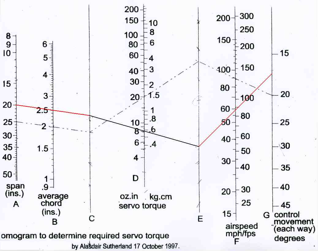 This number can be compared with the data that was provided in the December 2013 Ampeer. It is pretty much in the same ballpark as the Gadd and Tenney calculators. Note: Ignore the light dashed lines on the screen capture from the CAD program. They are on the nomograph from someone else's previous calculation. By Ken Myers With suppliers' servo torque specifications in question, I decided it was time to do some actual measuring. I built a servo torque measuring device. The idea for this servo torque tester came from an RC Groups thread named "Servo Torque Tester", Post #9. 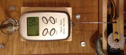 The photo shows a Micro Mark Digital Pull Meter attached to a servo arm with its hole one inch from the center of the servo screw hole. The servo is a Hitec HS-225 that is rated at 54 oz-in of torque. 55 oz-in divided by 1 inch = 55 ounces of force. 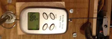 Next a standard servo arm was attached. The distance from the center of the screw hole to pushrod hole on this standard servo arm is 9/16" or 0.5625 of an inch. The amount of force supplied increased. The force is proportional to the arm length. 55 oz-in divided by 0.5625 inches = 97.8 ounces of force. 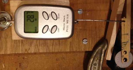 A servo arm of 2" was used next. 55 oz-in divided by 2 = 27.5 ounces of force. The longer the arm, the less the available force. As the servo arm length is shortened, the available force goes up. As the servo arm length is lengthened, the available force goes down. A Hitec HS-225 with a servo arm connection 1/2" from fulcrum yields about 108 oz. of force, while one 2" from fulcrum yields about 27 oz. 1963 Minnie Mambo Version 2 Electric Tribute
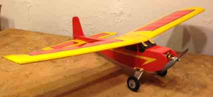
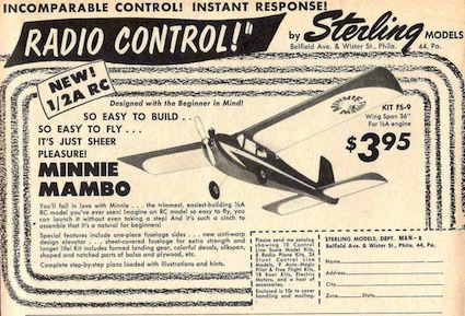
My first or second RC plane, exactly which is lost in my mind, was a 1963 Sterling Minnie Mambo. The other plane was a DEMCO DeBolt "Live Wire" RC Trainer. I had pulled out my original plans a couple of years ago with the intention of creating an electric powered tribute version. Unfortunately, the plans did not include a top view of the fuselage. I could not obtain the former widths. I had a spot of good luck last year when Joe Hass kindly offered to loan me a brand-new Version 1 kit. Using it, I was able to obtain the former dimensions. 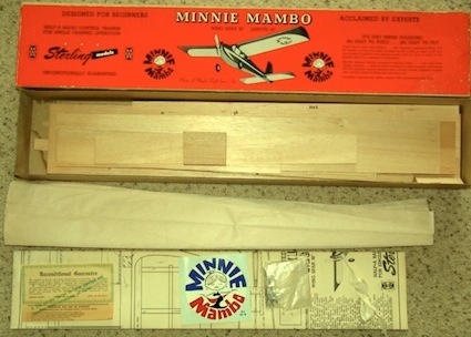
An ad from 1961 shows the Version 1. An exterior difference between Version 1 and Version 2 was that Version 1 had wire landing gear sewn to former F3 and Version 2 used a dural-style knock-off landing gear. Another exterior difference was that Version 1 had only one forward dowel protruding from the windscreen while Version 2 used two dowels. The actual fuselage side on Version 1 had a cutout for the cowl block in the fuselage side. On Version 2 the cowl block was inside the fuselage sides. Version 2 also had doublers added above and below the horizontal stabilizer. I also obtained a completed 1963 Version 2 airframe from Dick Flemming of Olivet, MI. 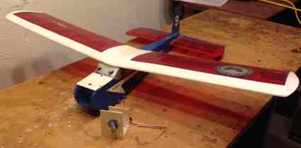 Dick's empty airframe, with no landing gear (none provided), weighed 332.9g or about 11.75 ounces. The fuselage was painted blue and the horizontal stabilizer and wing were, at some time, recovered in what appeared to be transparent red Monokote with white trim. Dick's original color was orange. Orange paint was found under the blue paint on the fuselage and under the transparent red Monokote on the wing center section and horizontal stabilizer. The former dimensions for the electric tribute version are based on the Version 1 kit and measurements from Dick's Version 2 airframe. CAD plans for a Version 2 Minnie Mambo, in .pdf format, have been available on the Internet since 2009. The plans were created by Gene Rock. If the plans are used, it can produce a model that is somewhat like a Minnie Mambo, but some of the dimensions and wood sizes are a bit 'off'. The former dimensions are incorrect and the concave curve is missing between former F5 (rear of radio compartment) and the tail. 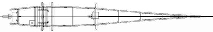
CAD Drawing of the Correct Top View I started my CAD drawing of the Minnie Mambo in August of 2012. I was not aware of Gene's plans at that time. I used my side view and the width dimensions from the Version 1 kit to create the formers for the new 'kit'. I also made several other changes to create the Min-E Mambo electric powered version which is both a tribute and restoration. Former F1, the firewall, was moved forward for mounting an electric motor. Former F2, in the battery compartment was changed from a full former to cross braces. Moving F1 forward created a larger hatch which uses a a magnet to hold it shut. The battery hatch is hinged from the side. The width of the cap ribs on the horizontal stabilizer was increased to 1/2" from 3/8" to allow for the use of iron on covering. There were some internal construction changes. It is difficult to notch plywood. F1 (the firewall) and F3 (the front of cabin former) were turned into constructions to aid cutting and sanding. The 3/32" plywood fuselage wing doublers (E) were changed to 1/16" balsa. Formers F3 and F4, the middle of the cabin area former, were opened up. The 3/32" balsa rear doublers, above and below the horizontal stabilizer, were changed to 1/16" balsa. That changed made F8, the rearmost 3/32Ó balsa former, a little less fragile. Most kits and plans were not very good in the early 1960s. The die cut wing tips were cut so close to the edge of the balsa sheet that the very "high part" of the rounded edge was missing. The top wing sheeting line was in the wrong place on the plans for both Version 1 and 2. This was verified using the Version 1 kit and plans, Version 2 plans and the 1963 wing in my possession. The kit provided horizontal stabilizer trailing edge was 1/4" instead of the correct 3/16" in thickness. The original kit plywood was 0.11" thick. That is about 7/64" and about 2.79mm The plywood was not aircraft grade, nor was it lite plywood as we think of it today. It was noted as 3/32" on the plans. 3/32" is 0.09375" or about 2.38mm. The two sheets of balsa containing the fuselage sides were 0.105" thick. That is just under 7/64" thick and about 2.667mm. The thickness of the fuselage sides was not called out on the plans. One piece of leading edge balsa in the Version 1 kit was rounded on one end and triangular on the other end. Once the new, modified fuselage and vertical fin and rudder were completed, the original 1963 wing and horizontal stabilizer were stripped. (Not an easy task!!!) 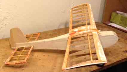 The plane was covered in red and yellow TopFlite Econokote with black Econokote stripping. The rectangular pattern on the wing and stabilizer were typical of the paint scheme on the planes at the club I flew with in 1963. The plane uses throttle and rudder. The rudder torque rod is controlled by a Hitec HS-50 servo. The power system consists of a Scorpion S-2205-32 outrunner, Castle Creations Thunderbird 9 ESC, Thunder Power 2S 450mAh LiPo and Cox gray 6x4 prop. The ready to fly (RTF) weight is 16 oz. One ounce of that weight is lead on the LiPo battery. Power is approximately 50 watts in per pound. The CAD plans and construction notes for the Min-E Mambo are on the EFO Web site. See the Min-E Mambo page for the plans. 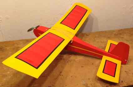
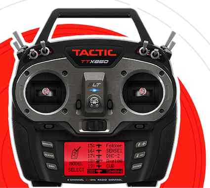
Tactic's TTX 850 was announced at last year's Nuremberg Toy Fair. This year, it seems like it will actually be available according to this press release. The press release was posted in this thread on RC Groups. It is not an old press release and is dated 2014. There will be an eight-channel dual diversity receiver available as well. More information is available on the Tactic RC Web site. With the hard winter and a lot of snow, the February meeting was held at Roger Wilfong's house. We thank Roger and his wife for taking us in on a cold, snowy Feb. 13. Their hospitality was very much appreciated. Thanks to both of you! 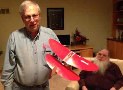 Roger Wilfong lead off the show and tell with his Stevens Aeromodel S-POU!Ş V2.4 Micro. He has flown it and noted that it has one interesting flight characteristic, it wants to fall backwards out of the sky if the flight angle is increased too much too quickly. The plane is well designed and quite an unusual subject. 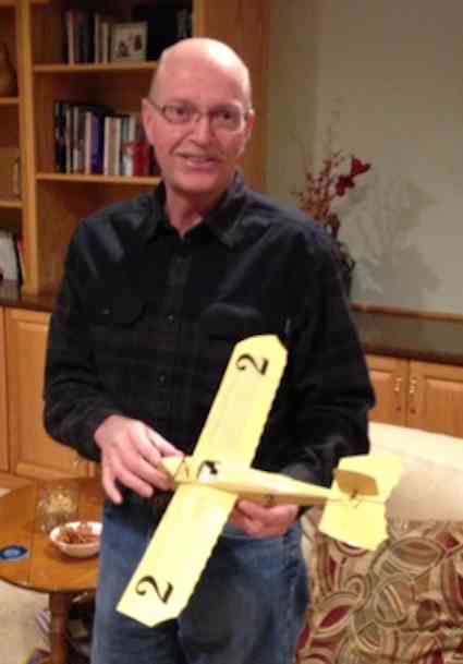 Denny Sumner brought along his recently completed 1911 Caudron Racer from Stevens Aeromodel. He noted that it makes up into quite a nice model. Care must be exercised in its building as the wood is quite thin. He's not flown it yet. 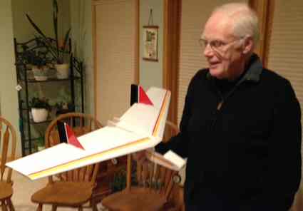 Arthur Deane brought along is recently completed Blinker. He was presented the kit for a submission he made to a magazine. At least that is his story, along with a new hat, but... the whole thing gets complicated from there. It was built from an Alien Aircraft kit. He said that it went together well, but there were some things that had to be figured out.  Ken Myers shared his recently completed Min-E Mambo. (More recently completed than he wanted. You really had to be there to understand that one.) It is his e-conversion version built as a tribute to his 1963 version. It is also a quasi restoration, as it uses the wing and horizontal stabilizer from a real 1963 built Minnie Mambo. 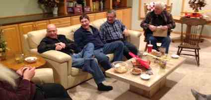 Hank Wildman brought along the nacelles to his Kyosho Lear Jet to ask Keith Shaw about his ducting and to share how he was creating the new fan units. There was a lot of talk and sharing of snacks on this fun evening. Again, thanks to Roger and his wife for inviting us in from the cold. 
Brighton Indoor Flying Date & Time Change
The Hamburg Flyers R/C Club have partnered with the Legacy Center of Michigan to continue to offer indoor flying. What: Indoor flying at Michigan's Largest Indoor Soccer Field. The Legacy Center is an inflated dome covering a 105,000 sq.ft. field with 85+ foot ceiling. There are separate flying areas for helicopters and quads (130 class and smaller), general sport flying, 3-D flying, and micro flying. When: Thursdays 11:00 a.m. to 1:00 p.m., Starting February 20th, 2014 and continuing until we can fly outdoors (which may be a while) Where: The Legacy Center (www.legacycentermichigan.com) Corner of Rickett and Winans Lake Road Brighton, MI 48116 Right off US-23 at the Silver Lake Road Exit (Exit 55) How Much: Only $5.00 per session (please bring current AMA card). We hope to see you there! Jim Young
From Pete Foss, Secretary Skymasters RC of Michigan, via email Just a reminder, we WILL be enforcing the rule from now on about charging at Ultimate Soccer in a fire resistant container. Please make sure you are charging in a LiPo sack, ammo box, etc. As you may have heard we had a LiPo battery fire during charging at Ultimate on January 27 that damaged the turf. As a reminder, our indoor rules require charging in a "suitable fire retardant container". In this case, several avoidable mistakes were made that culminated in a fire.
Ultimate seems to be taking the incident in stride but lets not have another one! Please bring a fire retardant container to charge in at Ultimate. I personally decided several weeks ago that I'd rather just charge at home and bring enough batteries for the 6-8 flights I usually get in a two hour session. Paul Goelz has some great safety tips and hints in this month's Skywriter. I encourage you to please give it a read. Pete Foss
From Paulo "Chispas" Faustino via email
Dear Ken, Hope all is well with you after storm Sandy. Here we have been "blessed" with light rain but the indoor season is already on full motion. I continue to read and appreciate the Ampeer newsletter but I am enjoying more and more the indoor side of the hobby. More than 4 years after his first flights, my motor glider, Grob, based on a Cessna Minium, received a new, more rigid wing. The new wing is shorter by 1cm. It was the size of the piece available, but I enlarged the chord to compensate for it and the greater weight. The fuselage is from the Cessna Minium with new turtle deck and motor cover from 1mm Depron, tail from 1,5 and 2mmm Depron. The wing is sanded to airfoil shape from 6mm Depron.
During the flights I tried to fly the most distance without motor and achieved the diagonal distance of the gym where we fly regularly.
Have good flights
From Owen Morgan via email
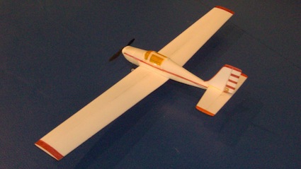
Dear Kenneth, Thanks for your suggestions for a power plant and servos for the Ryan NYP. I have purchased the components, but not had time to build the plane yet. I built an OSG glider with a V-tail. I call my version the OSG-X. OSG stands for one sheet glider because she is designed to be built from one sheet of Dollar Tree foam board. AUW is 180 grams and WCL is 2.2. I'll try to build the next one lighter... She glides well and climbs like a homesick angel with an APC 5.5x4.5 prop. The outrunner and ESC came from a retired RTF plane, so I'm not sure, but believe it's a 10 gram motor and a 10A ESC. I'm getting around 6 minutes of motor time on a 460mAh 2S 25-40C nano-tech. The motor is only used for short blasts at WOT for climbing. This gives me around 25 minutes of flying time when there are no thermals about. I would really like to use a folding prop on this plane, but am having problems finding any as small as 5.5x4.5. I suppose I could go with larger diameter and less pitch, but here is where I'm not sure what would perform similar to the prop I'm using. (Or perform better as long as I don't over-stress the motor, ESC, battery or airframe.) As she is, I have to be careful with the throttle. WOT in level flight would rip the wings off her in no time. The only props I can find that are anywhere near are from cermark.com. Their smallest offerings are 6x3 and 7x4. The rcgroups thread for the OSG is here. Regards,
April 4, 5 & 6 Seagate Centre To Reach Ken Myers, you can land mail to the address at the top of the page. My E-mail address is: KMyersEFO@theampeer.org |