 |
Flying High With Electric Power!
The Ampeer ON-LINE!
Fly the Future - Fly Electric! |
|---|
Site Table of Contents
| President: | Vice-President: | Secretary-Treasurer: |
| Ken Myers | Richard Utkan | Rick Sawicki |
| 1911 Bradshaw Ct. | 240 Cabinet | 5089 Ledgewood Ct. W. |
| Commerce Twp., MI 48390 | Milford, MI 48381 | Commerce Twp., MI 48382 |
| (248) 669-8124 | (248) 685-1705 | (2480 685-7056 |
 | ||
| Board of Directors: | Board of Directors: | Ampeer Editor |
| David Stacer | Arthur Deane | Ken Myers |
| 16575 Brooklane Blvd. | 21690 Bedford Dr. | 1911 Bradshaw Ct. |
| Northville, MI 48168 | Northville, MI 48167 | Commerce Twp., MI 48390 |
| (248) 924-2324 | (248) 348-2058 | (248) 669-8124 |
| The Next Meeting: Date: Wednesday, March 9 Time: 7:30 p.m.
Place: Ken Myers' house (address above) | ||
| LiPo Batteries: I Don't Know Jack! - Parts 1 & 2 Ken Myers starts his multi-part exploration of learning about LiPo batteries, facts and fictions. | The FMS SuperEZ PNP AKA SupREZ Review Part 1 of Ken's review of this plane. |
| Upcoming Keith Shaw Birthday Party Electric Fly-in 2016 Meet announcement from Dave Grife. | |
Parts 1 & 2 By Ken Myers For many Ampeer readers, this may seem to be a strange topic for me. Most readers know that I use A123 Systems 2300mAh/2500mAh LiFePO4 cells in almost all of my planes. I have a Thunder Power 2S 450mAh pack, that I use in my Min-e Mambo, and a 2S 500mAh pack in the Scorpion Backup Guard, that I use in my Sig Four Star Forty. I also have several small 1S packs for my Flyzone Tiger Moth for indoor flying. I actually started using LiPo batteries in early 2006. I used 4S and 5S 4000mAh 10C LiPo batteries from Skyshark and True RC, along with high discharge NiCad and NiMH packs. The LiPo packs worked well, the 5S weighed approximately 40% less than a 16-cell 3300mAh NiMH pack and had about the same usable capacity. Unfortunately, one of the LiPo battery drawbacks was quickly demonstrated to me. "I've been flying long enough that crashes are pretty rare. A plane that I was flying one of the True RC LiPo batteries in had an unexplained crash. There was no fire, but one of the expensive, for the day, LiPo packs had a dent in one of the cells. It was a goner. The other pack continued to provide good service and was sold with the Ryan STA it was used in, because by then, I was aware of, and using, A123 Systems cells. Over the years, and especially in the last few months, I had accumulated a lot of information and misinformation regarding LiPo batteries. It was time to organize both my thoughts and information. Starting at the Beginning I presented part of what I had learned so far in presentations at the January and February EFO meetings. The presentations include links to videos and Web sites that illustrate the topic being discussed. Part 1 (January EFO Meeting) Includes:
Part 2 (February EFO Meeting) Includes:
I believe that it will be well worth your time to check out this information. The FMS SuperEZ PNP AKA SupREZ Review
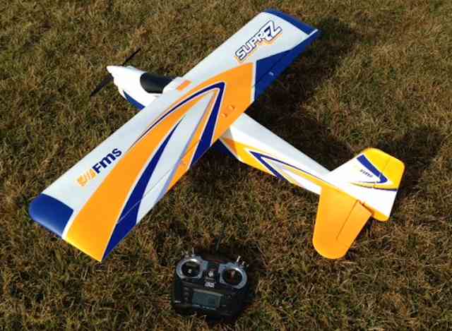 By Ken Myers, February 2016 Forward:
In the early fall of 2015, I decided to add the Multiplex Mentor to my stable of training aircraft. I went to the Tower Hobbies' Web site and found it on backorder. I visited the Multiplex Web site, in Germany, and found it not listed. It had been discontinued. While looking for a trainer similar to the Mentor, I ran across the TechOne Air Titan. The Titan is about the same size as the Mentor and required a similar power system. It lacked one essential feature, a top hatch for loading a battery. In my article "Freewing Pandora Review & Some General RC 'Trainer' Thoughts" in the September 2015 Ampeer, I noted three characteristics that I want in a trainer, besides being a gentle, 'good flying' plane. Those three characteristics were:
I recently remembered that there was actually a fourth characteristic that I wanted, an easily removable cowl. Removing the cowl on the Sensei, for the first time, was extremely difficult. It was glued on! I searched the Internet trying to find a trainer plane that had those four characteristics. I only found one, and set it aside in my memory for later. As fall changed into early winter, I became totally absorbed with learning as much about Lithium Polymer pouch (LiPo) batteries as I could. During my research period, I ended up with eight 3S 1000mAh LiPo batteries. While I was learning about, and testing, LiPo batteries, I received an email from my friend and flying buddy, Dave Stacer. He asked me if I knew about the FMS SuperEZ trainer. That was the plane I'd come across in my searching in the fall. In my mind, it is 'marginally small' for a decent trainer. It only has a 48" wing span. It does have a top loading battery hatch, conventional landing gear and a removable cowl. As a bonus, it does NOT have a lot of the white EPO foam showing. It is very colorful, due to its paint and stick on graphics, and it should present well in the sky with no modifications. I mentioned the 'presentation problem' in Part 2 of the Pandora review, "Why White?" The FMS Web site noted, "3S 1300mAh battery allows for 15 minute flight times". There is a video on the FMS Web site with some details, although it is called the SuprEZ Trainer on the video. SupREZ is a graphic on one of the wing panels, but the box and manual refer to it as the SuperEZ. The video is absolutely HORRIBLE at showing off its qualities as an introductory, beginner trainer. The RC Informer video review is a bit better and provided some interesting information. "I think it draws about 15 amps full throttle static on the ground."
The video is good at explaining and giving details about the model. To me, it looked like the throws he used, for flying in the video, were set too high for training. Bruce Simpson, of RC Model Reviews in New Zealand, has a good video covering the flying. With a lot of 3S 1000mAh batteries on hand, I figured that was close enough to a 1300mAh pack in weight and capacity to be used in this plane. The plane was ordered from Diamond Hobby, the only USA distributor I could locate for the PNP version, on Saturday, January 23. Shipping was free and the price of the plane, delivered, was $139.99. The RTF (ready to fly) version is NOT to be considered an option. Even though it includes a minimally acceptable radio system, LiPo battery charger and LiPo battery, it is a poor choice. The battery charger is of poor quality, slow to charge only through the battery's balance leads and potentially dangerous. The plane arrived at about 4:00 p.m. on Wednesday, January 27. The Specifications on the artfully decorated box:
There are very few parts in the extremely well designed inner foam insert in the well packed box, so it should have been a super easy assembly. Unfortunately, FMS chose not to include two small screwdrivers. Two small phillips head type screwdrivers are the only tools really needed for assembly. The FMS' Web site notes that the airframe is made of EPO (Expanded PolyOlefin) foam. No glue is required for assembly, but if it is truly made of EPO foam, I found it surprising that in the manual's Maintenance section, p. 12, it states, "Repairs to the foam should be made with foam safe adhesives such as hot glue, foam safe CA and 5min epoxy." Regular, not foam safe, medium thickness CA is used on EFO foam. Overall, the manual was just slightly better, in some aspects, than other Chinese manuals I've seen. The grammar is better than most Chinese attempts at English. There are quite a few 'typos', but they generally do not distract from the content. Unfortunately, there is a 'glaring' error on p. 10 regarding checking the C.G. (Center of Gravity). The diagram, at the bottom of the page is fine, although lacking a measurement in inches. The problem is that the text states, "1. The recommended Center of Gravity (CG) location for your model is (60mm) forward from the leading edge of the main wing (as shown) with the battery pack installed." Note that I put the word forward in bold letters. The position is actually rearward from the leading edge. I believe that most beginners would not notice the text and just use the diagram. 60mm is 2.3622" or about 2-11/32". The wing chord measures 230mm or 9". That makes the recommended CG 26.3% of the chord, which is a pretty good starting CG recommendation. Since 2-11/32" is a bit hard to measure, I'd recommend 2-5/16", or even 2-1/4", which would be 25% of the chord. Assemble the Model on p. 4 Step 1 of the assembly appears to start with installing the pushrods for the ailerons. (That turns out to be incorrect. Step 1 is actually on p. 7, setting up the radio.) The aileron hardware and pushrods are packaged together and should be dumped into a small bowl, so that none of the hardware is lost. The first assembly step, for setting up the ailerons, is to attach the control horns to the ailerons. That is pretty straight forward, if a screwdriver, that will actually fit the small screw heads, can be located. A white bath towel was doubled and spread over the work area so that any dropped screws would not bounce and 'disappear' on the floor. I found that a #0 phillips type screwdriver sort of worked with the very small screws. First, I "pre-threaded" the holes for the screws in the hollow posts provided on the control horn base. A screw was started with the #0 screwdriver. When the screw became hard to turn, and I feared 'rounding' of the screw slot, a regular pair of pliers was used to hold the screw head while the control horn was twisted. The pliers were then used to back out the screw until it was easy to turn with the screwdriver. FMS provided an extra screw of each length (long towards the front of the aileron and shorter towards the rear of the aileron). The same screw was used for 'pre-threading' all four screw holes in the two control horns. That screw was NOT used for assembly, due some rounding of the slot in the head. Even with the pre-threading, the task was more difficult than it needed to be and it took way more time than it should have. The next step was installing the pushrods between the aileron servo arms and the aileron control horns. The aileron servo arms were 'pushed forward' for shipping to bring them sort of flush with the wing's bottom surface. There is no mention in the manual about NOT pulling them 'out' or even moving them to neutral using the radio system. They really should NOT be moved manually. To get the servo arms to neutral, first I set up my radio system. (Actually, setting up the radio system first is noted on p. 7 of the manual. That note should really be at the beginning of the manual.) I set up a Tactic TTX650 transmitter for this plane. The model was named, channel 3, the throttle channel, reversed (that is required for this particular radio system using an ESC), and all of the trims centered. A Tactic TR625 receiver was linked to the transmitter using a 4-cell NiMH receiver battery I have for this purpose. That receiver battery is used for all of my radio system set up. I find it easier to do that way. Of course a LiPo battery, hooked to the ESC with the ESC hooked up to the receiver would work. If using that method, the propeller must be off. The propeller is off when the plane is shipped and again noted on p. 7 of the manual. After pulling the aileron leads out of their shipping cavity, the supplied "Y" connector was connected to each aileron lead. The "Y" connector was plugged into the aileron slot in the TR625 receiver and system turned on. As expected, the servo arms 'popped up' into the neutral position. The control horn outermost hole required a 1/16" drill bit run through it to allow the clevis pin to go through it easily. The clevis 'sleeve' keeper was slid onto the approximately 1.5mm diameter pushrod and up to the clevis. The pre-bent "Z" bend was inserted into the innermost hole of the servo arm. The clevis pin was connected through the outermost hole of the control horn. Why I chose this position is explained shortly, but remember what I said about the aileron movement in the video. A diagram on p. 9 shows the suggested hole positions for the servo arm and control horn for each moveable surface. It showed the outermost hole on both the control horn and servo arm for the ailerons. Unfortunately, there is no reference on p. 4, where the assembly begins, to the diagram on p. 9. It could easily be overlooked. Page 9 also notes the effect changing holes has for either the servo arm and/or control horn. That is a very good piece of information for beginners! When setting up any new plane, I like to use about 140 of angle movement for the moveable control surface as the initial maximum physical throw for the ailerons and elevator. The easiest way to figure that out is to measure the chord of the aileron or elevator at a given point, where the vertical movement will be measured. Divide that number by 4. That yields the desired initial maximum vertical movement, one way, up or down, for about 140 of angle movement. The aileron is rectangular and is 1-3/8" wide from the middle of the molded hinge line to the trailing edge. That width is known as its chord.
The FMS low rate recommendation, p. 8, is 10mm up/down. Giving both a high and low rate recommendation seems a bit 'odd' for this plane. (See: Who is this plane for?) The radio system was turned on and the clevises adjusted on the aileron control horns to align the ailerons' trailing edges with the trailing edges of the wing. It is a good idea to hold the small diameter pushrod with a regular pair of pliers while adjusting a clevis. The aileron vertical movement was measured. There was 3/8", or 12/32", up movement and 5/16", or 10/32", down movement on each aileron. That worked out to 9.525mm of up and 7.94mm of down. In a Tip on p. 9, FMS notes, "At first flight, fly the model in low rate." Since this plane is being set up as a basic trainer, for beginning pilots, I chose to go with even less than the recommended low rate throw and MY maximum initial throw of about 140. The differential was just a bonus because of the way the factory installed the aileron servo arms. Getting the aileron servo screws out would be very difficult, so I just left it that way. Finally the clevis safety 'sleeve' keepers were slid up the clevis and over the arms to keep the arms from separating. Weights and measures as received The measured wing span, at the trailing edge, which is the longest span, is 47.97" or 1218mm. The wing area is approximately, 47.97" x 9" = 431.73 sq.in. 12.18dm x 2.3dm = 28dm2 The area is actually less than that. The wing tip angles in from the trailing edge to the leading edge and the leading edge is rounded at the tip. For my calculations, I'll use 432 sq.in., even though it is a bit greater than actually measured, since 432 sq.in. is 3 sq.ft. The completed, one piece wing, with the unique twist lock wing bolts and "Y" harness weighed 10 oz. or 285.6g. The metal landing gear, two 3" wheels, nuts & bolts acting as axles and three landing gear bolts weighed 2.79 oz. or 79.1g. The fuselage was prepared for weighing by temporarily attaching the prop and spinner, and the elevator pushrod, clevis safety 'sleeve' safety keeper, elevator servo arm and servo arm screw. Step 2, on p. 4 shows the installation of the servo arm, pushrod, etc. for the rudder, but it was already completed on the model that I received. The fuselage and everything associated with it weighed 14.9 oz. or 422.8g. Note: It was nice to see that FMS included an extra landing gear screw and an extra screw to secure the horizontal stabilizer, but they did NOT include an extra servo screw for the elevator servo. An extra servo screw would have been nice. The horizontal stabilizer halves, joiner tube (Pipe) and two screws weighed 1.56 oz. or 44.2g. Total weight of the included parts, 29.34 oz. or 831.7g (It's going to be a little hard to hit "around 890g" flying weight, since a typical 3S 1300mAh pack weighs about 105g to 120g and no receiver has been added to the plane yet.) Preparing to add the horizontal stabilizer While weighing the parts, I had temporarily attached the elevator servo arm with the pushrod installed. I found that I had to use a 1/16" drill bit to get the "Z" bend into the servo arm hole. I hooked up the radio system, allowed the elevator servo to go to neutral, and then attached the servo arm with the pushrod installed in the innermost hole of the arm. The push rod was located on the outside of the arm to attach to the preinstalled control horn on the elevator. I pre-threaded the holes in the 'tabs' that hold the horizontal stabilizer halves to the fuselage. The hole for the joiner tube (Pipe) was too tight of a fit to slide in the tube. I had to use an 11/64" bit, by hand, to open it up enough for the tube to slide through. The tube was installed and then the horizontal stabilizer/elevator half assemblies were slid into position. Getting the elevator joiner halves to meet and slide into each other was a bit fiddly. The screws were screwed into their respective holes in each stabilizer half. I did end up with a thumb impression in one of the stabilizer halves. It was caused by my pressing so hard to get the halves to fit. A pair of regular pliers was used to hold the elevator pushrod while the clevis was adjusted so that the elevator trailing edge matched the horizontal stabilizer tip trailing edges. The safety sleeve was slid over the clevis arms. Both the elevator and rudder directional throw were checked. The elevator needed to be reversed for my radio. The landing gear assembly was screwed on. All of the spare parts were placed in one hardware bag and paper clipped to the manual for safe keeping. Setting up the vertical elevator movement demonstrates why recommending absolute vertical measurements, for moveable surface throw, is a bad idea. The manual indicated that the elevator pushrod should be connected to the innermost hole of the servo arm and outermost hole of the control horn, p. 9. That is how I set it up, as it provides the least throw possible. The low rate, p. 10, for the elevator is noted as 10mm (~25/64") up/down. It does not say where to measure the elevator vertical movement. If the root side chord of the elevator, with a chord measurement of 1-15/16" is used, the angle resulting from 10mm of vertical movement would be about 11.40 in one direction. If the tip side chord of the elevator, with a chord of 1.5" is used, the angle resulting from 10mm of vertical movement would be about 14.60 in one direction. This can't be, because with the same pivot point, the hinge line, the resulting angle of the surface has to be the same! Using the previously mentioned chord divided by 4 method for about 140, the root chord vertical movement would be 1.9375" / 4 = 0.484375" (~31/64") in one direction. At the elevator tip chord the vertical movement would be 1.5" / 4 = 0.375" or 24/64" in one direction. The measured vertical movement, in one direction, up, at the elevator root chord is 9/16" (36/64") and at the tip chord 7/16" (28/64"). That yields an angle of about 16.250 using both chords, which it should. This is the smallest physical amount of movement for this surface, with this servo arm, and this control horn. It is close enough to the numbers I was aiming to achieve.
Many folks might ask, "Why not just use dual rates or end point adjustments to reduce the servo throw using the transmitter?" My question right back at them would be, "Why not just set up the plane for an initial flight, correctly!" Beginners certainly don't need to worry about more things than are truly necessary. The manual does not show how to install the receiver. On p. 6 there is a paragraph that refers to fig14, but fig14 is useless, as well as the paragraph relating to the installation of the receiver. I temporarily tucked the power lead, with Deans connector, into the battery compartment. I noted the Deans connector, because a true beginner would need batteries with Deans connectors, so as not to have to do any connector changing. The elevator servo lead had been taped to the right side of the radio compartment. I removed the tape. The Tactic TR625 is a dual antenna, dual diversity, receiver. The antennas need to be 900 to each other. I used a couple of small pieces of NyRod yellow inner tubing to run the antenna leads through. They could have been just taped into place. Adhesive back Velcro was applied to the receiver. Since I plan on taking the wing off for transport, a 6" servo extension was connected to the receiver aileron slot. The servo extension makes plugging and unplugging the aileron connection much easier. The receiver, both pieces of Velcro, and the 6" servo extension weighed 0.48 oz. or 13.7g 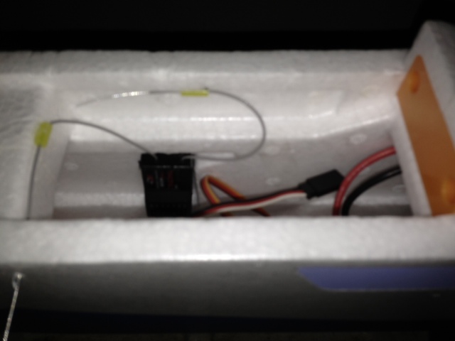 The paper was removed from the adhesive side of the Velcro to be stuck to the fuselage inside cabin side. A couple of drops of medium CA was applied to the adhesive side of the Velcro, as insurance, and CA kicker sprayed on the cabin side where the receiver was to be placed. The receiver was pressed into position and antennas run through the NyRod pieces. The antenna going across the fuselage exits to outside the fuselage. This is not really necessary, but why not? This is no scale masterpiece! The wing was fitted to the fuselage. The wing 'bolts' required a little bit of sanding on the top of the projection near the bottom of the bolt. That projection turns and slides under a piece of plastic to lock the bolt in place. Clearing the battery compartment: The somewhat tiny battery compartment, with an opening 1-3/4" wide and 3-1/4" long, has two hook-and-loop straps, near the front and back of the battery tray, to secure the battery in the plane. The top of the battery tray has a large piece of hook-and-loop fastener secured to it. There is a 1-1/4" x 2-1/2" piece of mating adhesive back hook-and-loop fastener attached to it. The mating piece was removed and set aside. Later, it will be used on the batteries for this plane. All of the mating piece adhesive back hook-and-loop fastener does not need to be used on one battery. The hook-and-loop fastener on the battery is just to keep the battery from sliding around, when straps are used. There really doesn't have to be a lot of it on the battery. I changed the supplied Deans connector to Anderson Power Pole (APP) connectors. I noted that the supplied 20-amp ESC power lead wire is most likely AWG #16, although it is not marked. Seven-sixteenths inch wide red tape was placed on the bottom of the wing to mark the C.G. The front of the tape is located 2-1/4" from the leading edge and the rear of the tape is 2-11/16" from the wing's leading edge. The location is based on a combination of my CG recommendation and the recommendation of FMS of 55mm (2-3/16") to 65mm (2-9/16"). 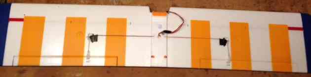 I temporarily assembled the wing, prop and spinner onto the plane. I slid a 105g 3S 1300mAh pack as far forward in the battery compartment as it could go. I noticed that only the most forward strap goes around the battery. The rearward strap does not come into play with a 3S 1300 pack. When holding the plane with my finger tips, on the red tape, on the bottom of the wing, I noted that the CG was just slightly behind the most rearward of the acceptable range of 65mm from the leading edge. For a beginner, if a 3S 1300mAh pack is to be used, I recommend at least 1/2 ounce of lead weight on the 'shelf', formed by a protrusion on the firewall, under the motor. Next, I slid the lightest 3S 1000mAh pack, 84.9g, as far forward in the battery compartment as it could go. I held the wing at the tape 'marks' again and noted that the plane was quite tail heavy. That was not a surprise. I removed the cowl to see where I could add some weight up front. That is a very simple statement, but it wasn't all that simple. It took three tries to find the correct phillips head type screwdriver to fit the cowl screw heads. I found that the screwdriver, that works best, is the same one that fits the landing gear screws well. The cowl screws are extremely long. They were seated firmly and did not want to loosen. After much vexation and a few mutterings, I got them out. I did NOT find a lot of room to add lead to the firewall or in the cowl. Four segments of the Great Planes Segmented Lead Weights were added to the cowl, just over the air flow cutout hole, with some minor modification to the foam projection on the firewall to allow the weight to fit. Another 2 segments of lead were added to the platform sticking out from the firewall under the motor. Each segment of the lead is marked at 1/4 oz. but actually weighs a bit more than that, 7.76g (~0.27 oz.) per segment. That is a total of 46.56g or 1.64 oz. added by the weight. The Final Ready to Fly Weight:
Checking the power system The power system, motor, ESC, prop and recommended 3S 1300mAh battery, should operate as delivered. A beginner should not need to verify it. This is how I verified that the power system setup was correct. The prop was checked for balance using a prop balancer. It was found to be acceptable right out of the box. Two problems presented themselves. Installing the propeller and three part spinner is described and illustrated on p. 10 of the manual. Unfortunately, how to tighten the plastic spinner cap, which contains the nut for securing the prop, is not explained. Just 'hand' tightening this nut did not seem like a good idea. I was able to slip a flat blade screwdriver in the hole(s) of the spinner cap and tighten it. The ESC should be setup for use as supplied. Unfortunately, the 'throttle range' is different with different radio system transmitters. How to calibrate the throttle to a specific transmitter is NOT explained in the manual. The programming of the ESC, using the throttle stick, is noted, but not explained, on p. 15, but how to calibrate the throttle, a one time setting, and enter the ESC programming mode is NOT. Programming the ESC with the throttle stick.
How to Calibrate the throttle from the ZTW ESC manual:
ENTERING THE PROGRAMMING MODE
The 'best', by my testing, 3S 1000mAh pack was charged. The fuselage was secured and restrained. A power meter, the Hyperion Emeter II, was placed inline between the battery and ESC to record the amp draw and voltage. The throttle channel was calibrated using the procedure from above. The motor was run and data recorded for 27 seconds. 27 seconds was from the time the motor started drawing current, higher than the idle current, to the throttle shutdown. The highest recorded amp draw was 18.8 amps at 11.84V, reaching full throttle, maximum amp draw, in 5 seconds. The throttle shut down occurred at 20 seconds from the time full throttle was reached. The average for the 21 seconds at full power, from maximum amps to shutdown of the throttle, was 17.67 amps at 11.5V. The median was 17.5 amps at 11.47V.
The power system numbers indicate that the 20-amp ESC should be sufficient and the power system can be considered, for polite conversation, 200 watts, although the true average will be less. After the power system test, the receiver failsafe was set up and verified as working. With an average amp draw of 17.67 amps for the first 20 seconds, I anticipate an average amp draw for a full flight to 80% of the 1Ah capacity (0.8Ah) to be 8.8 amps. It could be more or less, but that is my way of estimating an unknown average amp draw, 1/2 the maximum static average. The amp minutes are 0.8Ah times 60 minutes or 48 amp-minutes. 48 amp-minutes divided by 8.8 amps = 5.45 minutes, which is most likely the worst case scenario. I am really expecting 6 minutes flights to be the norm when training. For the initial check out flight, the countdown timer, of the Tactic TTX650, using the throttle to activate it, was set to 4 minutes. A throttle LOCK was setup on the transmitter. Upcoming Keith Shaw Birthday Party Electric Fly-in 2016
The Balsa Butchers will once again be hosting the "Keith Shaw Birthday Party Electric Fly-In" at their field near Coldwater, MI. The event will take place on Saturday June 4, 2016. It will be a one day meet this year. The event consists of Open Electric Flying with a "Special Guest of Honor Theme". Enjoy a day with the "Pioneering Master of Electric R/C Flight". 8 am - 5 pm Saturday, $10 landing fee. For additional information contact Dave Watson 517-250-6190 or email: flybuddy619@yahoo.com
The field will be open to guests to fly Sunday as well. Directions: Quincy is approximately 4.5 miles east of I-69. Clizbe Road is approximately 1.6 miles east of Quincy. The Flying site is approximately 1.5 miles south of US-12 on the west side of Clizbe Road. 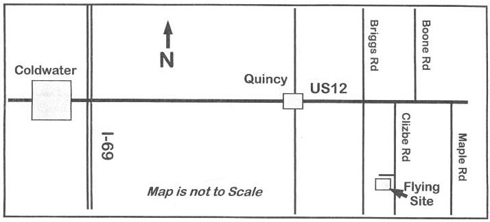 To Reach Ken Myers, you can land mail to the address at the top of the page. My E-mail address is: KMyersEFO@theampeer.org |