|
Flying High With Electric Power!
The Ampeer ON-LINE!
Fly the Future - Fly Electric! |
|---|
Site Table of Contents
| President: | Vice-President: | Secretary-Treasurer: |
| Ken Myers | Richard Utkan | Rick Sawicki |
| 1911 Bradshaw Ct. | 240 Cabinet | 5089 Ledgewood Ct. W. |
| Commerce Twp., MI 48390 | Milford, MI 48381 | Commerce Twp., MI 48382 |
| (248) 669-8124 | (248) 685-1705 | (2480 685-7056 |
 | ||
| Board of Directors: | Board of Directors: | Ampeer Editor |
| David Stacer | Arthur Deane | Ken Myers |
| 16575 Brooklane Blvd. | 21690 Bedford Dr. | 1911 Bradshaw Ct. |
| Northville, MI 48168 | Northville, MI 48167 | Commerce Twp., MI 48390 |
| (248) 924-2324 | (248) 348-2058 | (248) 669-8124 |
| The Next Flying Meeting: Date: Saturday, Oct. 7 Time: 10 a.m.
Place: Midwest RC Society 7 Mile Rd. Flying Field | ||
| Reminder About EFO Flying Season Meetings Ken shares that EFO Flying meeting dates are tentative. | Measuring a Battery Pack's Internal Resistance Part 2 Ken continues his discussion on how to measure this battery characteristic using more examples. He also corrects 'errors' that he was unaware of in Part 1. |
| Upcoming Midwest Swap Shop Upcoming November Midwest RC Swap Shop Info | ORGANIZE YOUR LI-PO BATTERIES WITH A NEW PRODUCT FROM RETRO RC Joe Hass shares a handy item for organizing your LiPo batteries in an ammo box. |
Dates given for the flying season EFO flying meetings are tentative. The date depends on the weather and may change from the one noted in the monthly Ampeer. The EFO Web site has the most current information posted. Also, emails are sent to EFO members if a date change is required. |
By Ken Myers Preface: In Part 1 of this article, in the September 2017 issue of the Ampeer, several techniques for calculating a battery pack's internal resistance were presented, as well as the theory behind calculating a pack's internal resistance. How the calculated internal resistance value can be useful to some folks was also noted. The acronym Ir, uppercase I and lowercase r, was used throughout the original article as an abbreviation for the battery's internal resistance. That acronym was used in that article to keep the nomenclature in line with the linked videos. In response to my announcement of the September 2017 Ampeer, posted on RC Groups, Ron van Sommeren posted a comment regarding the use of this nomenclature. He noted, "...we EE's (electrical engineers KM) would use Ri as symbol for internal resistance. First the symbol for physical quantity, followed by the index to specify it." Rint was noted in Part 1. IR (uppercase I and uppercase R) is the most commonly used acronym to indicate the internal resistance of a battery. Using all capital letters is the typical way an acronym is created. IR is used as the acronym for a pack's or cell's internal resistance in this article. Part 1 introduced a simple math formula for calculating the pack's internal resistance. Unfortunately, Ed's method, Ken's variation of Ed's method using the stabilized end open circuit voltage (OCV), Bruce Simpson's method and the Ivan Cowie's 2-Tier method, presented in Part 1, do not provide the pack's IR. Those methods produce an ohmic value that can be used for comparison purposes only. They do not indicate the expected loaded voltage from a given open circuit voltage (OCV) due to the voltage drop caused by the pack's internal resistance and amp draw, except for the time period used to gather the data for the ohmic value. Ken, why did you waste our time with those methods then? I was convinced that the methods were correct, as the results yielded an ohmic value. I mistakenly ASSUMED the value was the battery pack's internal resistance value. It was very, very difficult for me to give up that idea. It had been ingrained in me for decades. On August 21, 2017, a week after Part 1 was published, an article was located on the Internet that reinforced that starting the data collection, to yield a calculated IR, must be initialized from a stabilized open circuit voltage (OCV). The article titled, "All you wanted to know about batteries but were afraid to ask", is dated November 2014, by Nadim Maluf. Underlined words and phrases, and the use of a 'bold' font, were added by me to Mr. Maluf's abbreviated quotations to indicate significant statements by the original author. Use of the stabilized open circuit voltage (OCV), or OCV at equilibrium, is prominent in his article. "...The chemical potential in a rechargeable battery is the voltage measured at the terminals of the battery --- at equilibrium. ... one has to let the battery sit for a long duration of time to reach equilibrium, then make the voltage measurement. This voltage is then a direct measure of the SoC (state of charge KM). For a particular chemistry or type of battery ... this relationship is universal. ... for every battery that is made of the same chemistry. ...The graph below shows this relationship, (loaded KM) voltage vs. SoC, for a rechargeable lithium-ion battery ... As charge is removed from the battery, its voltage drops according to the relationship identified by the red curve. This relationship is known ... as the open-circuit voltage (OCV) function. Notice that capacity (in units of mAh) does not enter this relationship." 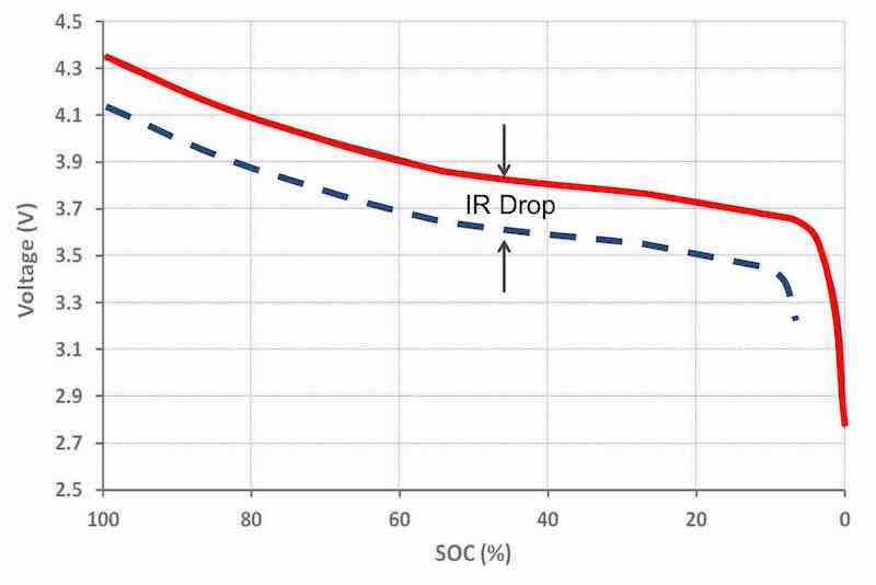 "... A chemical system ... is not in equilibrium when there is current flowing through the battery, ... the actual voltage at the terminals of the battery is a little lower than what you would measure in equilibrium. ... every battery has a little internal resistance to it. ... when there is current flow, the voltage is now lower by a value equal to the product of the current times the resistance ... This is illustrated in the chart above with the blue dashed curve. ... one can correct for this offset: measure the value of the internal resistance, multiply it by the measured current, then add it to the measured terminal voltage to obtain an estimate of the equilibrium voltage. ... " "... wait for durations of time ... then assume that it is close enough to the equilibrium voltage. ... waiting for long durations to make a SoC measurement is not terribly practical." "... correcting for the IR offset creates inherent errors. ... internal resistance of the battery fluctuates with current, temperature, and age ... " 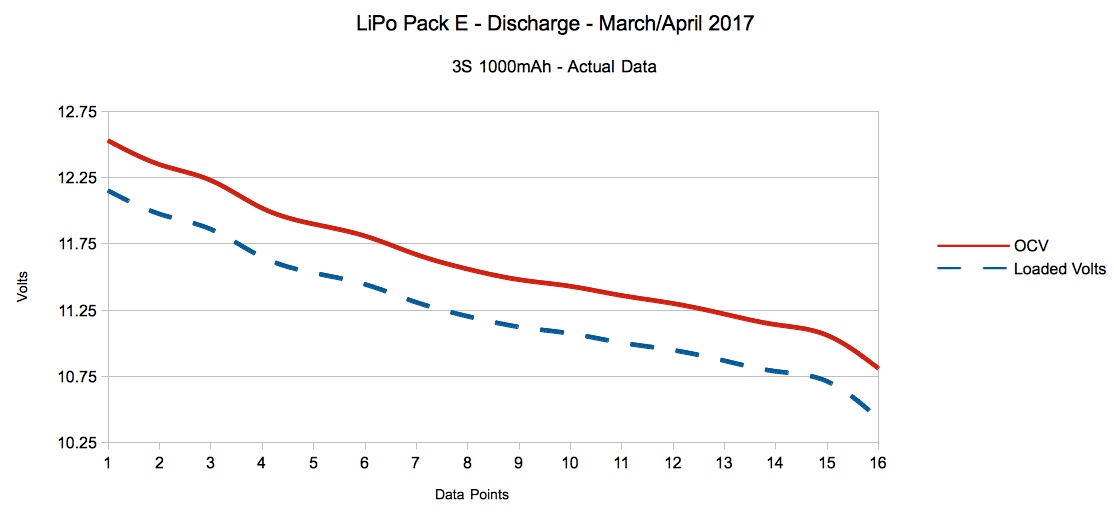 The graph above is similar to Mr. Maluf's graph. The graph demonstrates that the loaded volts drop in parallel to the open circuit voltage (OCV). The distance between the lines is the voltage drop, which is the result of the internal resistance multiplied by the amp draw. The values used to create the graph came from actual measurements that were recorded on a spreadsheet. When calculating the IR for batteries used in our power systems, the typical load might consist of some type of bulb or bulbs, acting as a resistor, or an actual resistor or resistors. Providing a load is fairly easy, but the bugaboo is time!!! The methods noted in Part 1 of the article yielded an ohmic value for the pack, but over a 'substantial period of time', that is 'for many seconds'. That value can be used to compare a pack to itself and to other packs of the same chemistry. While it is an ohmic value for the pack, it is not 'the' ohmic IR value for the pack. Using any of the methods discussed in Part 1 results in ohmic values that are only true for that method and that period of time period. This realization, after all of these years, caused me a lot of vexation. The terminology for this method may give you pause, if you are not a mathematician, and most of us aren't! The method involves graphing the slope for the voltages and amp draws from several measured values obtained by using different loads, which provide different amp draws, from the initial stabilized open circuit voltage. What??? Jack Sheldrake discusses this method toward the end his video titled, "EMF and internal resistance Unit 1" on YouTube. In the first part of the video he discussed the theory behind calculating a battery's internal resistance. The material is very similar to the linked videos by Steve4Physics in Part 1. The whole video is only 7 minutes and 49 seconds long. It is a good review, but the first part can be skipped by anyone who feels comfortable with the process. The important part starts at about 4 minutes into the video. After viewing the video you are probably going to go, "What the...!" The important word in the video was gradient. The gradient is also known as the slope. When graphing, the resulting slope value is the IR in ohms when the Y value (vertical) is volts and the X value (horizontal) is amps. I hear you!!! Again with the, "What the...!" Here is a real life example. Starting from the stabilized open circuit voltage, a 5 ohm resistance was switched on, voltage and current recorded, and then switched off. It was immediately followed by a 2 ohm resistance being switched on and voltage and current recorded, and then switched off. Immediately followed by the two resistors being switched on in parallel resulting in an approximately 1.428 ohm resistance, with its voltage and current recorded. All of the switching was done electronically. The results were four data points for voltage and four for current. A computer spreadsheet is much easier to use, and to understand what is happening, rather than using the complicated math formula for the data points to yield the slope. The slope is also known as the trend line. 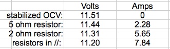
Initial Data Points
Note that the data positions need to be 'swapped' around to create the scatter graph. 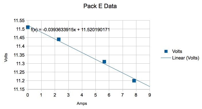
Scatter Graph The data points were graphed with the volts on the Y-axis (vertical axis) and current on the X-axis (horizontal axis). A straight line drawn between the points is the slope and the slope for this data is the pack's IR noted as a negative value. The scatter graph shows the data points as square boxes. A trend line/slope line was inserted onto the plotted data along with the formula used to create the trend line. Unfortunately, real life data does not usually end up in a perfectly straight line. The trend line creates a 'best' approximation. The formula on the graph notes the slope, which is the IR, as -0.0393633915. That means the meaningful IR is 0.03936 ohms, or 39.36 mOhms for the pack. The value of 11.5201190171 is where the trend line intercepts the Y-axis and represents the open circuit voltage as calculated by the formula. Again, it is not perfect. The measured OCV was 11.51, but it is reasonably close. A graph does not have to be created to get the slope (IR) and intercept (calculated OCV). The graph was used only to illustrate what is being calculated. Computer spreadsheets have a SLOPE and INTERCEPT function that will yield the results. 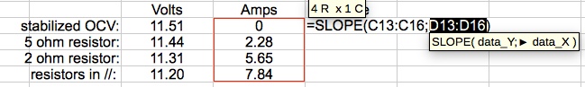 The first screen capture of the spreadsheet shows the slope function with the Amps values still highlighted. The Volts values had been previously highlighted. The symbol used separate the Volts values and the Amps values will depend on your spreadsheet. In this case it is a semi-colon, but other spreadsheets may use other symbols. 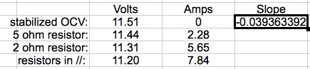 The final slope value -0.039363392, which represents the IR, is shown in the above screen capture. The intercept is calculated the same way, except the function is =INTERCEPT() with the Volts values and Amps values in the () and separated by the symbol your spreadsheet uses. 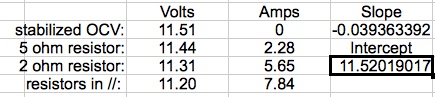 The final spreadsheet screen capture shows the words Slope and Intercept inserted into a column next to the Amps column. The values are in the cells underneath their respective words. The battery's internal resistance is about 0.03936 ohms and the intercept indicates an open circuit voltage of 11.52, which is close enough for our purposes. Time can never be completely eliminated when current is flowing. By definition an amp (ampere) contains time. An ampere is a unit of electric current equal to a flow of one coulomb per second. The resistors, even switched electronically, took some small unit of time to switch on and off and the calculation/measurement of the volts took some small unit of time, but the whole process took a much shorter overall time period than the 10 seconds noted with the first methods mentioned in Part 1. The resultant ohmic value, shown as the slope, is a much more realistic IR value for the pack than the previously mentioned methods. The values presented here, in the example, were gathered using the Vollrathd DIY IR meter. A parts list and schematic can be found on RC Groups.
What You'll Need: 1. A device, or devices, to measure and record volts and amps simultaneously.
2. A Load
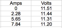
3. A switch that can handle the expected current 4. 14AWG or 12AWG wire 5. Appropriate connectors Build the Load Circuit I used two 12V 50W halogen bulbs, wired in parallel for loading the 3S LiPo packs. A 20A switch, purchased at Meijer, was wired in series with the load bulbs. I use Anderson Power Poles (APP) on all of my planes as the power connectors. It is extremely easy to wire connections in series with them. I also tried a 1.5 ohm 100W power resistor that I purchased from Amazon. It gave no specifications on the accuracy of the resistor. It measured 1.7 ohms. I prefer the bulbs. 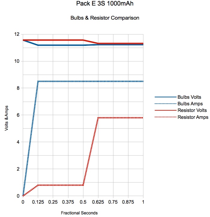 When the bulbs, or a resistor, are switched on, a couple of things happen in the first 1/2 second or so. The battery surface charge and any passivation effect 'kicks' in. The bulbs take a bit of time to heat up and settle into a fairly steady resistance, but so does the resistor. Select a Measuring Device I prefer the Emeter II set to 8 captures per second. An Eagle Tree Systems eLogger V4 could also be used. A power meter, or a pair of multimeters, used with a video recording device will also work. How to use this method was described in Part 1. The Procedure Once the pack is between 220C and 240C, the load, recording device setup and battery are all hooked up. The switch is turned on for a count of "one thousand and one", and then turned off. Only two points of the data are used. The first is the no load volts. The amps are zero since no current is flowing. The second data set is where the highest amp draw occurs with the highest voltage at that amp draw. 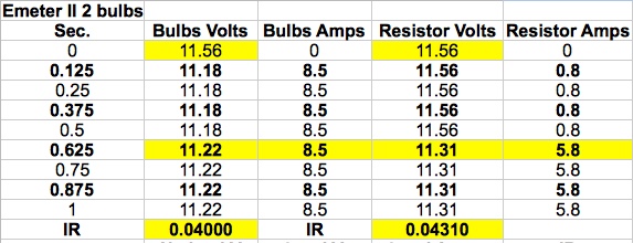 The table shows the data points, collected by the Emeter II, used for the pack's IR calculations using both the bulbs and a resistor. The values in the yellow cells were used to compute the IR. No load volts minus the loaded volts and the result divided by the amps. i.e. (11.56-11.22)/8.5=0.04000 ohms The process was repeated for the IR value using the resistor. 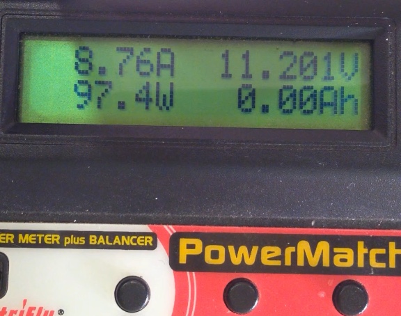 The screen capture shows the high amp draw with its corresponding highest voltage as captured via video using the ElectriFly Power Match. The No Load Volts were recorded as 11.523V.
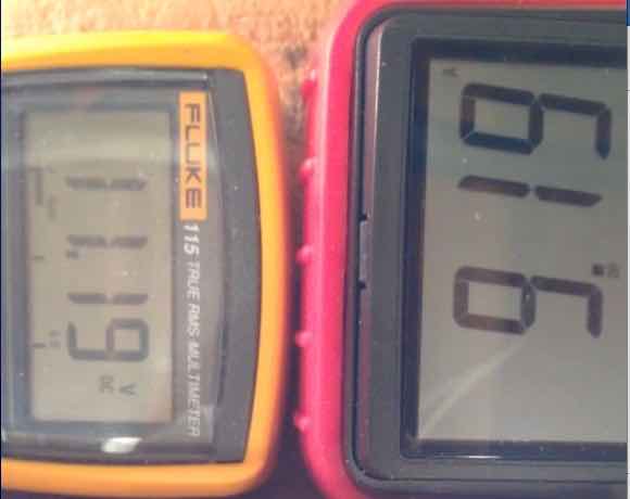 The screen capture shows the high amp draw with its corresponding highest voltage as captured via video using two (2) multimeters. The volts are on the left meter and amps on the right meter. The No Load Volts were recorded as 11.54V.
The three different methods of capturing the required data were for illustration purposes only. For results to be comparative, over time, and/or to each other, only one method should be used. 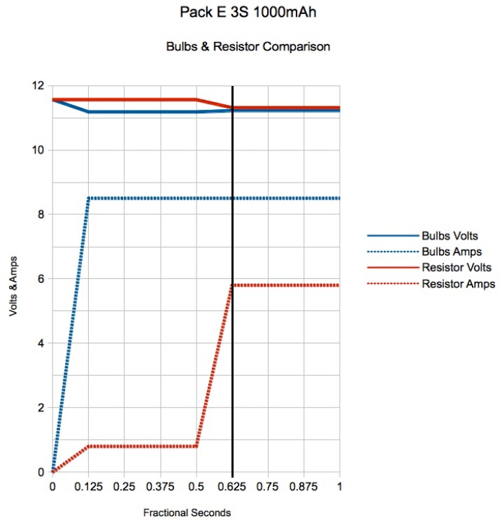 This graph is similar to the Bulbs & Resistor graph. It demonstrates why this method works. The black line at 0.625 seconds shows where the highest amp draw, with its corresponding highest loaded voltage, occurs. For 4S through 6S LiPo packs, a second set of similar bulbs should be wired in parallel and placed in series with the first bulbs. Alternately, a second equal resistance power resistor should be attached in series to the first set of bulbs to handle the voltage. Even though several different methods were used to determine the IR of Pack E, the results were surprisingly similar. Every attempt was made to equalize the pack temperature to about 220C, but it did vary some. The no load voltage also varied some, but was at about the storage voltage of 3.85V per cell. Slope: 0.03936
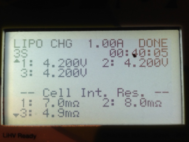
I mentioned using 'storage voltage' as the stabilized OCV in Part 1 and again in this article. I received an email from David Gray. He noted, "Many people used to believe and preach this (using storage charge KM), but it seems SoC has little to no effect on IR. I've personally done lots of testing and found IR consistent across normal operating voltage range for LiPos. I'd be interested to hear if you've seen otherwise." I have not seen otherwise, except for a small variation in the IR value when taken with the pack fully charged and then stabilized. The most important factor is that the no load voltage is taken from a stabilized pack voltage at a point where the voltage has reached equilibrium. I recommend 'storage voltage' because it eliminates the time necessary to wait for the pack's cells to reach a stabilized voltage, if they have been stored for awhile. The recommended temperature of 220C to 240C, which is 720F to 750F, is NOT a magic number. It is simply a temperature where we humans and battery packs are 'comfortable'. Again, it is convenient. Build and use a Vollrathd DIY IR meter. A parts list and schematic can be found on RC Groups. It can provide the data for a slope IR value or it will display an IR value based on the 2-Tier method. There are also two reasonably accurate commercial IR meters. The Wayne Giles ESR meter has been around a long time. It is easy to use and provides useful results. Although Wayne Giles is no longer producing the meter, it is still available. From the RC Groups page, "This meter is still using the design by Wayne Giles, software written by Phil Green and calculations like used in the Lipoly Objective Performance Calculation Tool (http://jj604.com/LiPoTool/) developed by RC Groups members John Julian (JJ604) and Mark Forsyth (mrforsyth)." It is available at Progressive RC. The Giles ESR Meter displayed 36.3 mOhms as Pack E's IR. This measurement included the whole pack's resistance including wires, connectors and cell interconnects. The worst cell recorded 10.84 mOhms as the cell's IR. The meter displayed 24 amps as the maximum continuous current for the highest IR cell. The weakest, highest IR, milliohm cell, is always used to derive the maximum continuous current without overheating, as it is the weakest 'link in the chain.' Earlier this year, Revolectrix introduced its version of an IR meter. It is also easy to use and provides useful results. 02/05/2019: I noted that the video that was originally linked below was deleted from YouTube; https://youtu.be/IHtZ_FCCmx0. The original video showed "Revo John", of Revolectrix, using his new "Honesty Meter". It was replaced today with the following video from Gone Heli Mad on YouTube. At first there was some controversy about whether this meter was a 'copy' of the Giles meter. It is not, and was designed by Fong of Revolectrix. It works to provide both a pack's and individual cell IR in a similar manner, but the actual functioning and displaying of values is different. Here Are Some Posts about Revo IR meter vs Giles
The Revolectrix IR Meter displayed 33.7 mOhms as Pack E's IR. This measurement included the whole pack's resistance including wires, connectors and cell interconnects. The worst cell recorded 9.83 mOhms as the cell's IR. The calculated maximum safe continuous current without overheating, using the highest cell mOhm value, is 24.7 amps. The manual methods of obtaining a pack's IR have been provided as an alternative to these three meters. The vollrathd, Giles and Revolectrix meters all provide individual cell IR values in milliohms. With any one of those meters, all of the individual cells in a given pack can be compared to each other, and if records are kept, the individual cells can be tracked over time. Using "A Simple LiPo Performance Tool", a maximum continuous safe current, without over heating the pack, can be derived for the pack. The calculations used by 'the tool' for the maximum continuous safe amp draw without overheating rule of thumb are integrated into the coding of the vollrathd IR meter and Wayne Giles ESR meter.
The results are in amps. The formula cannot be used directly with the whole pack's IR value. The pack's IR value will always contain the external resistance of the wire, connectors and cell interconnects. That value will be slightly higher than the sum of the individual cells presented by the three IR meters. Using the pack's individual cell average IR can provide a useful guide to the maximum continuous current, but individual cell 'health' cannot be determined. For Pack E, the Emeter II values for the pack IR calculated to 0.04000 ohms or 40 milliohms. The individual cell average is then 40 mOhms divided by 3 cells = 13.3 mOhm. The square root of 6 times 1000mAh divided by 13.3 mOhms is 21.2 amps. SQRT(6*1000/13.3)=21.2 The suggested LiPo Tool rule of thumb maximum continuous current will vary slightly depending on the method used to derive the pack's IR and the calibration of the tool or tools chosen to calculate the pack's IR, but it will still be close enough to be useful. In his Instruction Sheet for the ESR meter, Wayne Giles states, "In real flying the LiPo will be subjected to surges and a practical safe surge is probably about 40% greater than the safe continuous current for the region of 10 seconds or so. This represents doubling the heat dissipated within the pack for the duration of the surge." To calculate the maximum current for 10 seconds multiply the maximum continuous safe current, without overheating the pack, by 1.4.
Is it accurate to use? Some chargers display a pack or an individual cell IR value. Is it accurate or usable? A video on YouTube, "LiPo Charger IR Function vs. Pro ESR Meter" by Joshua Bardwell, provides an answer to the question. Note that in the video Josh is using pack IR in milliohms. Some chargers only display cell IR in milliohms. Like Josh, I found that my chargers do not do well at presenting useful, and more importantly, consistent IR values. The charger that I am using now shows two of the three cells of Pack E at close to the same IR value and one cell at about 1/2 their value. The vollrathd, Giles, and Revolectrix meters all show values that are much closer to each other. I have no faith in the ohmic values presented on my Revolectrix Gt500. I have communicated this 'problem' to Fong, of Revolectrix, on several occasions and there has been no resolution. In an email exchange with Fong, I noted the following cell ohmic values for Pack E as displayed on the Gt500 charger and the Giles ESR meter.
Gt500 Screen Capture of a Different Pack The photo shows the same 'problem' with a different pack. Again, the Giles meter did not show that kind of individual cell IR value variation. I exchanged a lot of this data with Fong, including many, many photos, similar to the one presented here. Personally, I have no faith in IR values on chargers that only calculate the IR value during the charge. Some chargers, like the iChargers, can calculate an IR value by applying a brief discharge. As Josh showed in his video, even these can yield problematic or questionable pack and cell IR results. If you want to 'keep a handle' on the health of your pack(s) over time, going down to the cellular level, the vollrathd DIY IR meter, Giles ESR meter and Revolectrix IR meter are for you. If you are just curious about various packs' IR values, a simple power meter and smart phone can give a simplistic insight into the pack's IR value. Knowing the pack's IR value is just one more tool to use to keep LiPo packs 'happy' and healthy. I could not find a way to 'step through' the video I captured on my iPhone 5 frame by frame when using a power meter, or two multimeters, to find the highest amp draw with the corresponding highest load voltage. I transferred the video to my MacBook Pro computer and stepped through it frame by frame by pressing the right arrow key. I believe there should be a similar way to do it using a Windows computer. November 5, 2017, Midwest RC Society 29th Annual RC Swap Meet
Admission Charge
Vendor Table Cost
For Information
Directions
THIS IS ALWAYS THE BEST & LARGEST SWAP MEET IN SE MICHIGAN! ORGANIZE YOUR LIĐPO BATTERIES WITH A NEW PRODUCT FROM RETRO RC
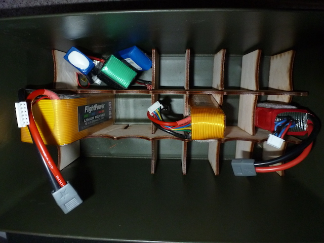
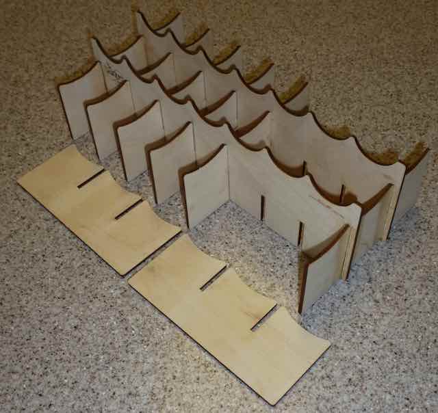
For those who use ammo boxes for storing Li-Po batteries there is always a problem with organization. It is far too easy to just randomly stack the batteries. You then have to dig to find the one you want. Mark Freeland, at Retro RC, has come up with a laser cut solution called the Ammo Box Divider. Available in 3 sizes the interlocking egg crate design give you the flexibility to reconfigure the layout as your needs change. I found it best to glue the end pieces in place with epoxy to hold the shape. Then as my needs change I simply rearrange the dividers. I can easily put two 5 cell packs together as shown while accommodating a variety of other sizes too. Three sizes of the Ammo Box Dividers are available for 16, 21 and 24 cells. All are laser cut from Baltic Birch Plywood. 16 cell $15.98 http://retrorc.us.com/batterybox1-3.aspx 21 cell $25.98 http://retrorc.us.com/batterybox1-3-1.aspx 24 cell $29.98 http://retrorc.us.com/batterybox1-3-1-1.aspx 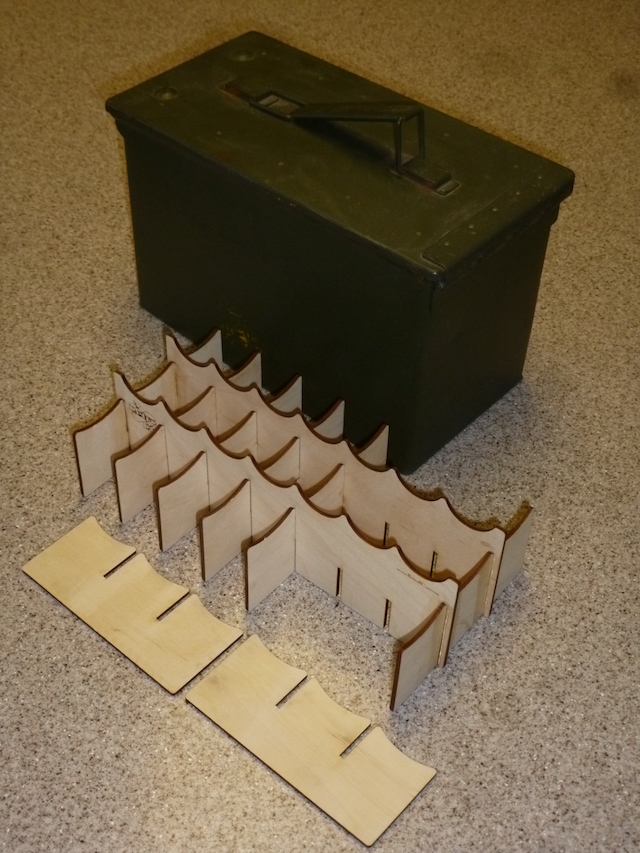
Visit your local retailer or Retro RC at http://retrorc.us.com/ or call 248-212-9666. To Reach Ken Myers, you can land mail to the address at the top of the page. My E-mail address is: KMyersEFO@theampeer.org |