|
Flying High With Electric Power!
The Ampeer ON-LINE!
Fly the Future - Fly Electric! |
|---|
Site Table of Contents
| President: | Vice-President: | Secretary-Treasurer: |
| Ken Myers | Richard Utkan | Rick Sawicki |
| 1911 Bradshaw Ct. | 240 Cabinet | 5089 Ledgewood Ct. W. |
| Commerce Twp., MI 48390 | Milford, MI 48381 | Commerce Twp., MI 48382 |
| (248) 669-8124 | (248) 685-1705 | (2480 685-7056 |
 | ||
| Board of Directors: | Board of Directors: | Ampeer Editor |
| David Stacer | Arthur Deane | Ken Myers |
| 16575 Brooklane Blvd. | 21690 Bedford Dr. | 1911 Bradshaw Ct. |
| Northville, MI 48168 | Northville, MI 48167 | Commerce Twp., MI 48390 |
| (248) 924-2324 | (248) 348-2058 | (248) 669-8124 |
| EFO Flying Meeting: Saturday, October 6 Time: 10 a.m.
Place: Midwest RC Society 7 Mile Rd. flying field Everyone with an interest is WELCOME Proof of AMA membership required to fly | ||
| Radio Review: FlySky FS-i6X Transmitter and iA6B Receiver Ken reviews this very inexpensive 6-ch computer radio system. | Upcoming Midwest RC Society Swap Shop Info Info on this upcoming November event. |
| How to Calculate Average Amp Draw for Your Electric Powered Model Airplane and I Couldn't Do That Again If I Tried Ken discusses how to determine the average amp draw for a power system and a weird coincidence when doing so. | |
By Ken Myers Preface: I have been flying Tactic radio transmitters and receivers since May of 2013. The Tactic TTX650 transmitter, predecessor to the currently unavailable TTX660, has worked well and reliably for me for 5 years now. I have two TTX650s. They are easy for me to program and they just work! There is no reason that I WANT to change. The FlySky FS-i6 kept popping up in both online reviews and YouTube videos. "The FlySky FS-i6 is a great entry level 6-channel telemetry 2.4ghz computer transmitter..." is a typical review found online. This is not the FS-i6X that is reviewed here. It is the FS-i6 predecessor being reviewed. Another one is "Flysky Transmitters: what to know before you buy". It includes a brief look at all three versions of the FlySky FS-i6; FS-i6, FS-i6S and FS-i6X. "Review of the i6 Not i6X" Nov. 11, 2016 on Propwashed by James states, "My initial thought was the FS-i6 would be a good entry-level radio. After using it, though, it's hard to call this radio "entry-level" anymore." Many of the video reviews on YouTube, for the FS-i6, had titles similar to "FlySky FS-i6 Best Beginner's Radio" with 126,674 views. I watched the video review by Bruce Simpson for the FS-i6, NOT the FS-i6X. I found some of Bruce's comments interesting;
Several of the quality "issues" Bruce noted in the video have already been addressed by FlySky in the i6X. The receiver, that was shown in Bruce's video, was the FS-iA6B. The receiver that came with my FS-i6X was also labeled FS-iA6B. They do not have the same labels on them. Bruce's receiver noted the receiver input voltage as 4.0-6.5V and mine is noted as 4.0-8.4V. I noted online, especially on RC Groups, that someone is providing updated and enhanced firmware for the FS-i6. The person who developed the 'alternate' firmware is not associated with FlySky. "What finally convinced me to give the FS-i6X a try was the video by iforce2D on YouTube. The video is named, "FlySky FS-i6X and X6B receiver second look", Nov. 21, 2016. Chinese suppliers and vendors have circumvented the FCC certification for their equipment. Before ordering the FlySky FS-i6X, I checked the FCC site to see if it was actually sent through the FCC certification process. System verification can be checked at the FCC Grantee Code Web site. Here is what I found on the FCC Web site:
Receiver: N4ZFLYSKYIA6B
After verifying that it was FCC certified, I downloaded the users manual, in .pdf format, from the FlySky Web site. The 34 page manual IS NOT searchable. This was a real problem once the unit was received. Scrolling and searching for something you thought you read takes quite awhile. The good thing about the manual is that the English is quite good. Unfortunately there are too many errors and omissions in downloaded manual. The way the sections are organized does not seem as logical as it could be. The transmitter batteries installation is in Section 3 of manual after the section where information was given about the receiver and hooking up the servos and receiver battery. The System Setup of the transmitter, which is universal to the transmitter, is located in Section 7. The Function Setup, which is specific to each plane, is located in Section 5. Statements from the manual are in bold font and my comments are not. Page 4
Page 5
Page 6
Page 8
2.3 Receiver Overview
Page 9
Page 10
Page 11
Page 12
2. Check operating distance: one operator hold the transmitter, and another one moves the model away from the transmitter. Check the model and mark the distance from where the model starts to lose control. - exactly how is that done? There is no reduced RF output range check available. Warnings in this section
Page 13
Page 15
Part 6. Helicopter Functions - again no mention of Menus and how to navigate. Page 21
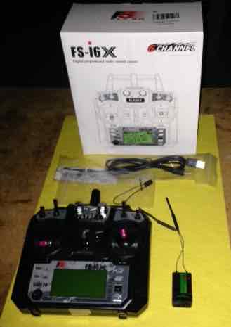
The FlySky FS-i6X was ordered on March 19 through Amazon Prime at a cost of $58.50. If I had ordered a Tactic TTX660 with a TR625 receiver, at that time, it would have cost $149.98 with my Tower Hobbies club membership and free shipping. The Tactic system is about 2.5 times as expensive as the FlySky System. The unit arrived on March 21. FlySky is the original equipment manufacturer (OEM) for Eachine, iRange, and HobbyKing's Turnigy TGY series. Each of the 'brands' can be found with different receivers in the package with them depending on who the brand is targeting. All of the versions of the i6X appear to be the same transmitter with different names on them. It does not appear that HobbyKing has a Turnigy TGY i6X at this time. The box for the system contained; a Quick Start Guide, the FS-i6X transmitter, the FS-iA6B receiver, a bind plug, and a cable for updating the firmware. There was no manual in the box. Luckily, I'd already downloaded it from the FlySky Web site. The Quick Start Guide is a 5 page fold out sheet. One side is printed in Chinese with English on the other side. The Quick Start Guide's font is EXTREMELY small. A quick read of the Quick Start Guide, using a magnifying glass, showed the same warnings as given in the manual. Overall there was really no useful information presented in the guide. There was no information in the guide regarding the receiver. The first thing I did with the transmitter was to wiggle the sticks to get their 'feel'. The stick assemblies/gimbals felt loose to me, and had no tension or resistance to my moving them. Too me, they had a horrible feel to them, or really no 'feel' to them at all. Stick 'feel' is very subjective. Throughout the summer of 2018 I let many of my flying buddies give me their opinions about the 'feel' of the sticks. Some folks liked them and others thought they were sort of okay. The FS-i6X appears to have the same gimbals as the FS-i6, its predecessor. There is a review online of the i6 that states, "The gimbals feel pretty good..." and "They feel nice and smooth and have a good center...". The gimbals on the i6X in my possession do NOT center well, as can be seen on the display screen in the System menu. I had read online, or saw in a YouTube video, that the non-ratcheting throttle could be tightened. I removed the back of the transmitter and found that only the tension on the non-ratcheting throttle stick could be tightened. I tightened the throttle stick screw. Before replacing the back cover of the transmitter, I inserted four Duracell AA batteries into the battery holder. No batteries come with the transmitter. I notice that the springs that provide pressure on the individual batteries in the battery holder are about 1/2 the size, and force, as the ones in the Tactic TTX650. The transmitter turned on when the switch was pushed up. Next the manual suggested plugging the servos into the receiver and connecting a battery to supply power to the receiver. The servo and battery connectors plug in at end of receiver, not on the top. Neither the manual or labeling on the receiver indicates the polarity of the plugs. The receptacles for the connectors have small slots in them just above where the actual connector plugs in. The little slots looked like they should take a Futaba style plug with the rib on the Futaba connector indicating the signal wire. That appeared to be a correct guess. 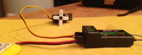 The battery and servo connectors were plugged in with the negative wire, as shown in the photo, on bottom of case for both a 4.8V NiMH pack and the servos. The transmitter was turned on and then the receiver battery was plugged in. Since the receiver was pre-bound to the transmitter, everything worked. I unplugged the receiver and turned off the transmitter. The FS-iA6B weighed 16g/0.56 oz. compared to my Tactic TR625 at 9.65g/0.34 oz. 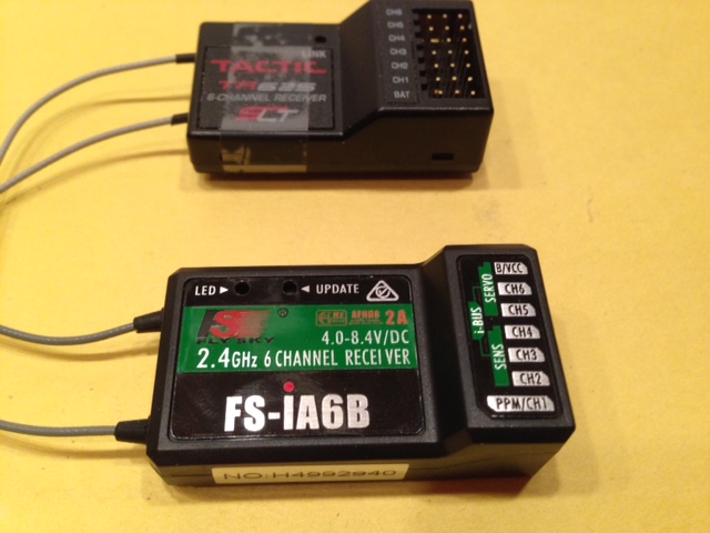 The photo shows the FS-iA6B and a comparable Tactic TR625 receiver. The FlySky receiver is considerably larger. 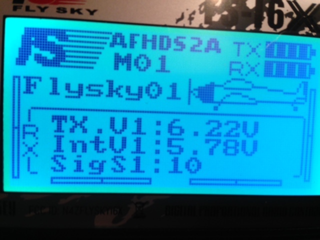 While the transmitter was on, and the receiver plugged into the external NiMH battery, I noted that the bright LCD screen showed the battery voltage of the transmitter (TX.V1), the battery voltage of the receiver pack (IntV1) and something called SigS1. It seems that SigS might mean signal strength, or possibly signal status, but there is no indication of that in any of the literature. An up to eight character model name had not been entered yet. The default of Flysky01 showed on the screen. The default icon of a plane was also visible. M01 indicates the position in the available 20 model memory. The graphic in the upper right hand corner of the screen indicates the relative remaining capacity of the transmitter (TX) and receiver (RX) batteries. The values used to create the relative capacity remaining can be changed for the receiver but NOT for the transmitter. The backlight goes off very quickly and there is no provision to set the time that it is on to a longer interval. The short backlight time can sometimes make the programming harder than it should be. The screen is difficult to see when the backlight is off. Because of the graphics used on the front of the transmitter, the buttons, on the face of the transmitter are extremely difficult to read. The buttons are labeled "UP", "DOWN", and "BIND KEY" to the left of the LCD screen and "OK" and "CANCEL" on the right of the screen just above the on/off switch. The "OK" and "Cancel" buttons are used for different purposes depending on what screen is on in the menu and how long the button is held down. A quick press on the "OK" button is sometimes an enter button for a menu item. From the main screen, a long press/hold for a few seconds enters the programming menus. (I found that by trial and error and checking Web sites. Actually, some Web sites/videos had it wrong. KM) 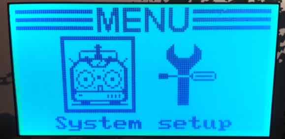 Upon entering the programming mode, there are two sub-menus available. System setup (icon: transmitter) and Function setup (icon: wrench & screwdriver respectively). What can be changed in the menus is noted in the manual. Sometimes what is being changed, when it is necessary to change it, and how it should be changed is a bit unclear. For example, in the RX Setup there is a servo frequency setup. I had never seen that before. I had to look up servo frequency on the Internet. 50 Hz seems "standard" for RC servos using PPM. I don't think this has any effect on PWM. Therefore, I didn't need to change it as it doesn't seem to relate to PWM, which I am using for my airplane set up. In the Systems menu I looked up the Firmware Version. It is FLYSKY FS-i6X 1.0 30-Mar-2017. Looking at the stick movements associated with the model I was setting up, I found that Channel 3, the throttle, did not need reversing as it does on Tactic and Futaba transmitters. Channels 1 and 4 needed reversing for the way the RUS 2-4-10 servos were mounted in the airframe. The Function Setup menu was chosen and then Reverse Function (5.2). It was very easy to do. The second programming I wanted to do was to mix the rudder with the ailerons so that my RUA-2-4-10 3-channel plane uses the same stick movements on the ground and in the air as a 4-channel plane. The mix worked when I mixed the rudder as the Master, channel 4, with the ailerons as Slave, channel 1. Both sticks are active when the "rudder" servo in the plane is plugged into the aileron channel (channel 1) of the receiver, but not when the rudder servo is plugged into the rudder servo (channel 4). When the rudder servo is plugged into the rudder slot (channel 4), only the rudder works and not the ailerons. Doing it either way on my Tactic TTX650 and TR625 receiver allows both sticks to always function. While I was programming the mix, I noticed the beep associated with a key press or alarm is very low. There is no way to make the beep louder. The transmitter sounds an alarm if all of the switches are not in the "up" position and the throttle is not all the way down. The rotating variable switch positions do not sound an alarm by default. They might if they are an active switch. By default they are off. The model was given a name in the Systems menu, Model name menu (7.2). The model was named RUA, which used only three of the 8 available characters. A throttle lock was created using one of the three two-position switches. There were two steps involved. In System setup, Aux. switches, switch D was turned on. In Functions Setup, Throttle hold, Hold was turned on and the Value set to 0%. When switch D is in the up position, the throttle works normally, when switch D is flipped down, the throttle will not function. The other 2 two-position switches, the three-position switch as well as the two variable position switches were not used in the setup. There was a hint that came up in the Throttle Hold (5.13) section of the manual. "To return a setting to default, press and hold the "OK�" key for 3 seconds." I had to use that hint when I mistakenly set up the voltages in RX setup thinking I could change the alarm on the battery. The alarm and capacity for the transmitter battery cannot be changed by the user. There is a 'hint' that the transmitter and receiver share information. Section 8 of the manual is RX Setup. Failsafe (8.3) is in that section, but for the failsafe to work, the settings have to be in the receiver. All the rest of the Section 8 functions also need to be in the receiver. I set up the failsafe (RX Setup 8.3) on the transmitter with throttle at 100%, rudder at -1% (that's right rudder, elevator at -8% (that�s up elevator) and aileron at 0%. It is very hard to do accurately. I lost my first settings because forgot to press and hold the "Cancel" key after setting up all 4 channels. The failsafe was tested by turning on the transmitter and then plugging in a power battery. The throttle was advanced slightly. The plane was held firmly. The transmitter was turned off. Once the transmitter was turned off, the motor stopped running and the the rudder and elevator went to the positions that were programmed into the failsafe. It worked as expected. I attempted to find a way that two servos could be plugged into two different channels to provide independent adjustments for aileron control. I couldn't find a way to set up two servos for independent aileron servos. A "Y" harness must be used for two aileron servos. The literature implies that this is a 6- AND 10-channel radio. It only becomes a 10-channel radio when iBus and PPM are functioning. For an airplane, using PWM, it is a 6-channel radio system. On April 26, 2018, the system was flown in one of my RUA 2-4-10 trainers for the first time. First Roger Wilfong and I ranged checked the radio by walking away from each other. He had the transmitter and I had the plane with the receiver in it. He would give an elevator command followed by a quick blip of the throttle and then I'd walk another 50 paces. When I reached the distance from him that I thought I would not exceed when flying the plane, I called it good. I flew the plane in a normal training fashion. There appeared to be no radio RF link problems at any time. The sticks just didn't feel right to ME, but the whole flight was well controlled and the plane did what I asked of it. I continued to fly the system in this plane through the flying season of 2018. Beginners and seasoned pilots flew the plane using this radio. When I asked the seasoned pilots how they thought the radio felt and worked, they noted that it was okay. Pros:
Cons:
I cannot recommend the FlySky FS-i6X system for beginners, or actually anyone, given the poor quality of the sticks with no adjustable tension, and poor centering. Having no way to do a reduced RF range check is unacceptable. Not being able to set the battery alarm voltage for the transmitter is not good. Having no timer, or timers, is a big negative for this system. Even with a recent slight price increase, it's cheap for a 6-channel computer transmitter and companion receiver. The unit that I have has worked and flown the RUA 2-4-10 through the flying season with no signs of any glitch. Midwest R/C Society
Location
Our Admission Charge Hasn't Changed in Years!
Vendor Table Cost
For Information and Table Reservations
Directions
THE BEST & LARGEST (AND MAYBE THE ONLY) SWAP IN SE MICHIGAN! IMPORTANT NOTICE! DUE TO SCHEDULING CONFLICTS AT VENUE, THE ANNUAL NOVEMBER SWAP SHOP WILL BE ON SUNDAY, NOVEMBER 18, NOT the 1st Sunday in November!
Return to "What's In This Issue" How to Calculate Average Amp Draw for Your Electric Powered Model Airplane, and I Couldn't Do That Again If I Tried
I previously noted that I could not recommend the FlySky FS-i6X because it doesn't have a timer; specifically a throttle "ON" timer. In my article "Advice for Getting Into Flying Radio Controlled (RC) Airplanes", I describe the importance and usefulness of a timer in the section titled, "Another Item Needed - a Timer". I also describe how to use the timer at the flying field. It is found�here. An approximate estimate of the average amp draw for a specific plane and power system can be made using a count down throttle timer and the milliamp hours (mAh) or amp hours (Ah) returned to the battery by a charger. There are many variables involved in creating the estimated average amp draw. The estimated average amp draw can be determined when the plane is flown consistently in a specific manner and in the same type of flying conditions. Wind velocity, ambient temperature, flying field elevation, pilot, type of flying mission and other factors are just some of the variables. Another variable is the charger's recorded mAh returned to the pack when it finishes charging. Once a balance charger enters "balance mode", it is not only charging, returning mAh to the cells, it is also discharging individual cells. It is not necessary to know the average amp draw for a specific plane, its power system, its mission and pilot, but it is another 'fun' aspect of the hobby. 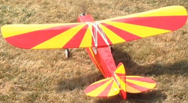 While flying the various versions of my highly modified Flite Test Simple Cub, I kept some records pertaining to the mAh/Ah used by the battery, that is returned by the charger, over a recorded battery on flight time period. The countdown timer on my Tactic TTX650 is toggled by the throttle position. The records included the mAh returned to the battery by the charger and the throttle ON flight time in minutes and seconds. Using this data, I was able to determine the average amp draw over the recorded flights. The average amp draw equals the capacity returned by the charger divided by the time. For me, it is easiest to use the amp hours (Ah) / hours (h). To change mAh to Ah, divide the mAh by 1000. The formula to change minutes and seconds to hours is; (minutes / 60) + (seconds / 3600)
Of course all of these numbers could be rounded, as this is only an estimate. 0.12 hours is certainly adequate. If the Ah returned to the battery was 0.339 (339mAh) then 0.339Ah / 0.12 hr = 2.825 amps as the average amp draw for the flight. About 2.8 amps is good enough. All of the battery packs are 3S 1000mAh/1Ah packs. That means that, for long battery life, I should not take out more than 800mAh/0.8Ah. 80% of the batteries stated capacity. Here is my recorded data including the rounded average amp draw: April 30 Dinogy 6 min. 340mAh/0.34Ah, Avg. 3.4A
The following include two flights on the same pack without recharging.
I had a an 'interesting' coincidence while calculating the average amp draw on two different days with two different 3S 1000mAh packs. Yes, I am positive that I recorded all of the data correctly.
Even without doing the math, it can be seen that this plane, flown by me, at the same flying field, following the same flight regimen, yields an average amp draw of about 3.5 amps. 0.8Ah (the amount to safely discharge to) divided by 3.5 amps equals 0.2285714 hours = 13.714286 minutes = 13 minutes 43 seconds. It can be seen that I am right on the cusp of doing two 7 minute flights when using a 3S 1000mAh pack using my standard flight regimen for this 3-channel plane. The powered segments of the flights include, rise off the ground (ROG), circuits in both directions, low passes, slow and low horizontal figure eights, loops, stall turns, touch and goes and any other 3-channel aerobatics I feel like throwing in. For the remainder of this flying season, I will continue to do two 7 minute flights per battery charge. I will keep a close eye on the mAh/Ah returned to the pack. Editorial Comment: I am still at a loss as to why many of the folks on the Flite Test forum regarding this plane are using, or trying to use, 3S 2200mAh packs in this plane. And look at the comments in this search of the forum. To Reach Ken Myers, you can land mail to the address at the top of the page. My E-mail address is: KMyersEFO@theampeer.org |