|
Flying High With Electric Power!
The Ampeer ON-LINE!
Fly the Future - Fly Electric! |
|---|
Site Table of Contents
| President: | Vice-President: | Secretary-Treasurer: |
| Ken Myers | Richard Utkan | Rick Sawicki |
| 1911 Bradshaw Ct. | 240 Cabinet | 5089 Ledgewood Ct. W. |
| Commerce Twp., MI 48390 | Milford, MI 48381 | Commerce Twp., MI 48382 |
| (248) 669-8124 | (248) 685-1705 | (2480 685-7056 |
 | ||
| Board of Directors: | Board of Directors: | Ampeer Editor |
| David Stacer | Arthur Deane | Ken Myers |
| 16575 Brooklane Blvd. | 21690 Bedford Dr. | 1911 Bradshaw Ct. |
| Northville, MI 48168 | Northville, MI 48167 | Commerce Twp., MI 48390 |
| (248) 924-2324 | (248) 348-2058 | (248) 669-8124 |
| The Next Flying Meeting: Date: Saturday, Sept. 3 Time: 10 a.m.
Place: Midwest RC Society 7 Mi. Rd. Flying Flied | ||
| Thank You Hobbico, Joe Hass & the Ultimate Soccer Arenas Ken shares info on this well attended event. | A Couple of Designs from John Hoover Designs;The Mega Bat & DAS FLEDERMAUS Joe Hass shares a couple of new John Hoover designs. |
| A Very Good Charger for Your 12V Field Battery Keith Shaw shares info and does a short review on the NOCO Genius G7200. | Initial Safe Center of Gravity Range, AGAIN Once again, Ken discusses the importance of using an ISCG and how to locate it. |
| Upcoming CARDS Electric Fly-in Electric Fly-in Announcment | |
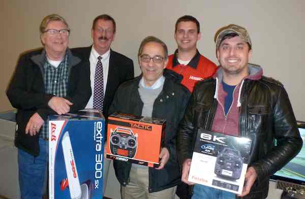
By Ken Myers and with Input from Joe Hass On Monday March 28, 2016 from 7 PM to 9 PM and again on Tuesday March 29, 2016 from 10 AM to 2 PM, Hobbico visited the Ultimate Soccer Arenas, 867 South Blvd., Pontiac, MI 48341, with their Pre-Toledo Show preview. Joe Hass put this great event together for us. On Monday evening, there were a lot of RC items on display and several new products were previewed. Josh Schiff presented many of the new items he'd brought up here for us to preview. On Tuesday, Josh, demonstrated many of the products during the regularly scheduled Skymasters' Indoor flying session. Prizes were raffled on Monday evening. Ken Myers won a flyzone extra 300 SX. (Thank you so very much Hobbico and Mr. Joe Hass!) Marcus Zervos won a Tactic TTX850 transmitter. Marcus is just getting started in this great hobby. He had just finished up a kit built Kadet. The TTX850 should come in very handy for him! Mike Vanston won a Futaba 6K. Mike had gotten into quads last year with an old 6 channel Futaba. He's an up and comer who needed a new radio. Josh used the gathering to present a multi-rotor to 5 year old, budding aviation enthusiast, Isaac Vickers. Isaac is the son of Shannon Vickers, an A-10 Wart Hog pilot with the local Air National Guard. Shannon and Isaac were to join the gathering last year but Shannon was deployed to Afghanistan. Those in attendance recognized Shannon's efforts with an unsolicited round of applause. In addition to all of the new products, the modelers in attendance, through the 50/50 raffle, raised $300.00 for the Salvation Army. There were also raffle prizes given out on Tuesday during the indoor flying session. I want to thank Joe, Hobbico and all of the folks at the Ultimate Indoor Soccer Arenas for putting on this fine program. Once again Joe, thanks for all you do for our local flying community and thanks for helping get several great pilot raffle prizes for the 32nd Mid-America Electric Flies! Joe, thanks for the following photos too! 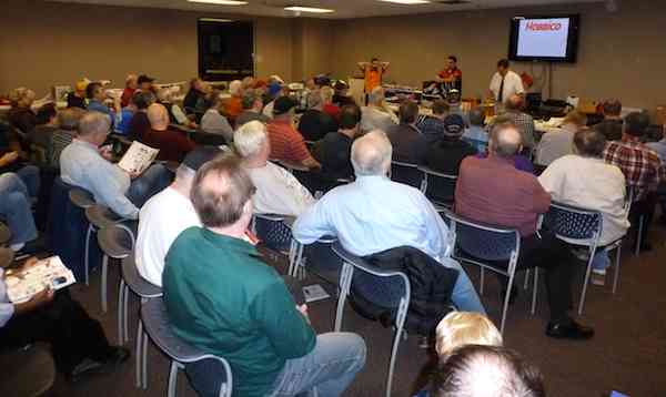
Just some of the folks attending the event.
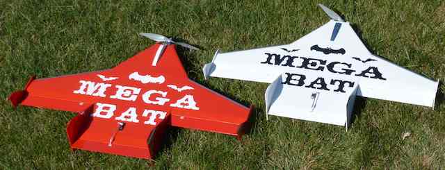
A Couple of Designs from John Hoover Designs;
Ken, I did a review for Park Pilot magazine on the Mega Bat that was designed and distributed by John Hoover at Flight Line Hobby in Lake Orion, MI. This is a neat aircraft that goes together quickly and flies well. Joe 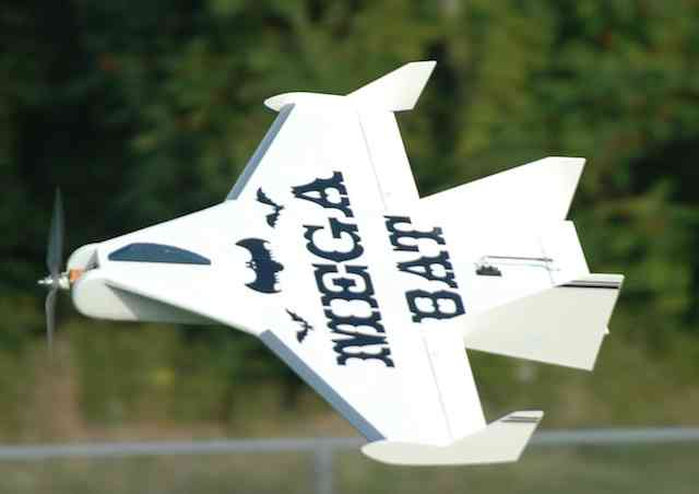
Click on photo for link to this plane & from John Hoover via Joe Hass
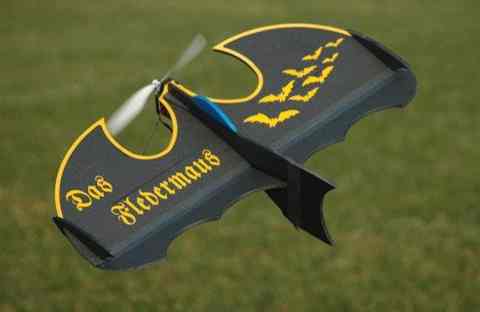
The DAS FLEDERMAUS was designed as an unusually shaped, small, fun aircraft for sport flying indoors or at a park. Featuring black flat foam, plywood and carbon fiber construction the FLEDERMAUS has a 23.5" wingspan with 340 sq. in. of wing area. Weight is 6-8 ounces. Being small and one piece when fully assembled, it is easy to transport. All you need is a motor, electronic speed control (ESC), battery, adhesives and radio equipment capability of elevon mixing. A complete power and electronics package including a 2204-21 pancake motor, 8" X 4.3" slow flyer electric prop and ESC is available directly from Flight Line. The DAS FLEDERMAUS can be easily customized to include a parachute drop and lights. The DAS FLEDERMAUS builds quickly and is fun to build and fly. The DAS FLEDERMAUS kit sells for $39.99. Stop by the shop to see the DAS FLEDERMAUS, call John at 248-814-8359, email aspectav5429@yahoo.com or visit www.flightlinehobby.com Dealer inquiries for the DAS FLEDRMAUS and all of Aspect Aviation hardware and kits are welcome. John Hoover, Flight Line Hobby, 248-814-8359 A Very Good Charger for Your 12V Field Battery
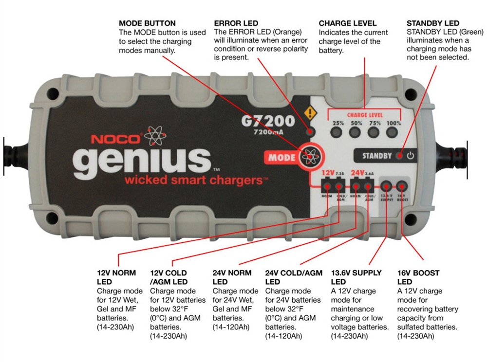
My ancient automatic Die-Hard charger started to misbehave and I decided it was time to retire it. Consider this a mini-review and recommendation of my chosen replacement. I use one or two deep-cycle AGM* "wheelchair" batteries (Panasonic LC-LA1233P, 33 amp-hr) for my flight line charging source. One is built into a field box that also carries one transmitter, two chargers and some tools. It usually goes to the field with me for evening or small-to-medium plane flying. I have a second one that can be plugged in parallel to charge the big packs and/or lots of flying. (* AGM (absorbed glass mat) is a special design glass mat designed to wick the battery electrolyte between the battery plates. AGM batteries contain only enough liquid to keep the mat wet with the electrolyte and if the battery is broken no free liquid is available to leak out. KM) After much searching and reading, I selected the NOCO Genius G7200, for about $90. (A search on Google revels a lot of sellers. There is also a YouTube video about it. The NOCO Web site shows the various charging 'modes'. KM) I was actually able to talk to a competent design engineer who patiently answered my specific questions on charge profiles and voltage end-points. The charger is completely automatic and will even remember your previous charge settings. It can charge 12 volt regular and AGM, 24 volt regular and AGM, and advanced AGM+. It has a mode so you can use it as a 13.8vt 6amp power supply, and a "repair cycle" for 12 volt cells to help reverse the two aging processes, sulfating and stratification. Two additional nice features are that it is about half the size of the old charger and only weighs a few pounds due to switching-supply design, instead of the heavy lead slug linear transformer. How does it work? All my tests so far have gone well and I am duly impressed. I set it for 12vt-AGM using the single button that steps through the options. The charger stays on stand-by until the battery is connected. The charger goes through a testing sequence before ramping up the current. BTW, I chose the G7200 which charges at a max of 7.2 amp. These AGM shouldn't be charged faster than 10 amps, so the choice is appropriate. They do make a 15 amp model (G15000), but it is quite a bit more expensive and somewhat larger and heavier. There are a series of 4 LEDs to indicate charge level. The power supply feature works as noted, it is reasonably well filtered and has minimal hash on the output. I will test this more later, so please don't go using it to power delicate electronics until I get a chance to test it more thoroughly. The repair cycle did bring an old corrupted AGM back from the dead. It was 40amp-hr when new, but had dropped off to under 25amp-hr quickly, so I discontinued using it and bought the two Panasonic AGM batteries. It had been sitting in my basement for about 8 years and was DOA. In the first 4 hour repair cycle it is back to 12vt and tested out at about 30amp-hr. I am going to do a few more charge-repair-discharge cycles to see if it gets better. I also have some ***really*** old AGM batteries that I took out of a decommission UPS system. I will have to see if it can revive those. If you find yourself in need of a good field battery charger, this NOCO Genius gets my nod of approval. Keith Initial Safe Center of Gravity Range, AGAIN
The term CG (center of gravity) range, as used in this article, refers to the fore and aft, or longitudinal, balance range for safe and controlable radio controlled flight of a model airplane. ISCG (initial safe center of gravity) refers to the fore and aft balance range where an initial, maiden, flight of an RC plane should be successful, as long as the control surface throws are not too extreme and the rest of the aircraft is reasonably well designed and proportioned. For conventional designs, with a main wing and horizontal stabilizer, the CG range location is between about 5% to 15% ahead of the aircraft's Neutral Point (NP*) on the Mean Aerodynamic Chord (MAC*), with the ISCG range between the wing's AC (25% of the MAC) and a point 10% ahead of aircraft's NP on the MAC.
In "Avoiding Some 'Crashes'", in the the June 2016 Ampeer, I stated, "I have noted over and over again, here in the pages of the Ampeer, that the center of gravity (CG) or CG range given by the supplier is usually wrong for a maiden flight!", and "Always, always, always, before any maiden flight, calculate the initial flight center of gravity (CG) yourself." I inadvertantly ommited the word range from my original comments, and the following excerpt, but it should be CG range, not just CG. There is no single, acceptable, correct CG. It is always a range. I also noted, "If you do not know how to calculate the initial safe center of gravity (ISCG), please use the following articles in the Ampeer as a reference." Finding a Starting CG From Sam Kilgore and Fine-Tuning the CG by Keith Shaw< varioProps & More From: Scott Black The March EFO Meeting - includes using a Vanessa CG rig In "Initial Safe Center of Gravity (ISCG)", Parts 1 and 2, I referred to the Web site "Welcome to Model Aircraft: Aerodynamics, Beginners' Guide and lots of info about R/C Model Aircraft". The section on aerodynamics includes information and term descriptions regarding the CG range and flight stability. There is also a CG calculator available. I also mentioned that the CG was incorrect for the FliteTest Old Fogey in the June and July 2016 Ampeers. To demonstrate why the given CG was incorrect, I created a Web page, linked to videos of the FT Old Fogey on YouTube. In the majority of the videos, that I listed as 'fails', the fail was exacerbated by the incorrect placement of the CG. Unfortunately, the designer gave only one point of reference for the CG, the apex of the airfoil. As it turns out, the apex of the airfoil is actually behind the neutral point (NP) of the aircraft. I posted the flight of my Old Fogey 1.22x prototype, with revised CG range, on YouTube. Ali Potter posted some comments regarding my choice of CG for the Old Fogey 1.22x on the YouTube page. I decided to share how I calculated the CG range and ISCG range for this plane. I drew a CAD equivalent showing the plan form top view of the Old Fogey, with the measurements based on my version, which is 1.22 times larger than the original. This gave me the dimensional numbers to use in the preveiously mentioned CG calculator. 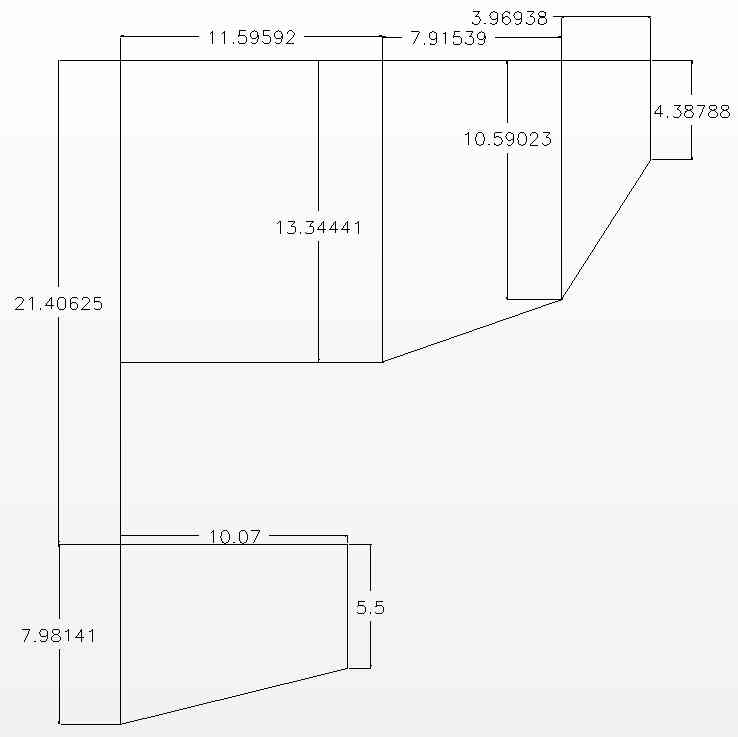 The Old Fogey has an atypical layout for a conventional design. In his article "Basic Proportions for R/C Model Aircraft", Model Airplane News, November 1996, Andy Lennon noted that from the wing 1/4 MAC to the horizontal stabilizer 1/4 MAC, the tail moment, the typical distance is 2.5 to 3 times the MAC for a high wing aircraft. Mean Aerodynamic Chord (MAC), the average chord for the whole wing. (The horizontal stabilizer has a MAC as well. KM). The 1/4 wing MAC distance to 1/4 MAC horizontal stabilizer distance for the Old Fogey design is about 1.5 times the wing chord, which is considerably less than 'typical'. From Aerodynamics: Stability Concepts, "Static stability is proportional to the stabiliser area and the tail moment. You get double static stability if you double the tail area or double the tail moment. Dynamic stability is also proportional to the stabiliser area but increases with the square of the tail moment, which means that you get four times the dynamic stability if you double the tail arm length." What all this means is that the shorter the tail moment is, the farther forward the CG range and ISCG range will be compared to a more typical design with the same wing and horizontal stabilizer but a longer tail moment. This shift is 'allowed' for in the CG Calc program. The note says, "Choose Low Stabiliser Efficiency if the tail is close to the wing's wake or behind a fat fuselage in disturbed flow." Both of these conditions occur with the Old Fogey design. With the low efficiency stabilizer in mind, the numbers were entered into the calculator. 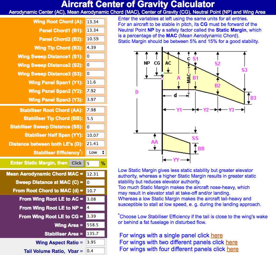 The results yielded the mean aerodynamic chord (MAC - 12.31"), aircraft's neutral point (NP - 4" from the leading edge of the root chord), the wing's aerodynamic center (AC - 3.08" from the leading edge of the root chord) and the CG location for a specific percent of static margin. A 5% static margin is shown in the screen capture, but static margins of 10% and 15% were also used and noted. See Aerodynamics: Stability Concepts Neutral Point (NP), the Aerodynamic Centre of the whole aircraft. The CG should be ahead of the Neutral Point (NP). Aerodynamic Centre (AC), It has been found both experimentally and theoretically that, if the aerodynamic force is applied at a location 1/4 from the leading edge of a rectangular wing at subsonic speed, the magnitude of the aerodynamic moment remains nearly constant even when the angle of attack changes. In order to obtain a good Longitudinal Stability, the Centre of Gravity CG range should be close to the main wings' Aerodynamic Centre AC. Static Margin is expressed as a percentage of the MAC. For conventional designs (with main wing and horizontal stab) the CG location range is usually between about 5% to 15% of the MAC ahead of the aircraft's Neutral Point (NP) on the MAC. The definitions of NP, AC, Static Margin and MAC were taken from the previously noted Web site page and edited by me for brevity and/or clarity. 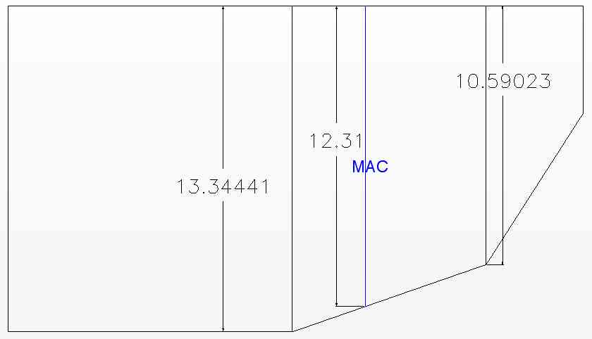 The wing plan form shows the MAC at 12.31". It falls in the second panel, as shown in the wing shape diagram. 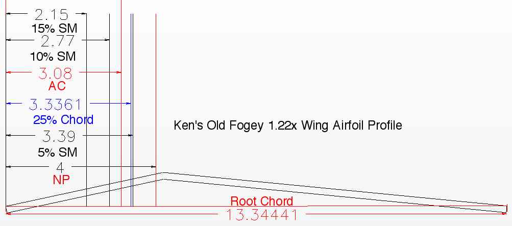 A root chord airfoil profile was created. The root chord airfoil profile shows the positioning of the aircraft's NP, wing's AC and static margins of 5%, 10% and 15% of the MAC on the root chord. The 25% Chord position on the diagram denotes 25% of the root chord, and differs by about a 1/4" from the AC, which is 25% of the MAC. The root airfoil diagram demonstrates that the aircraft's neutral point (NP) is forward of the airfoil's apex. That is not good for longitudinal stability! 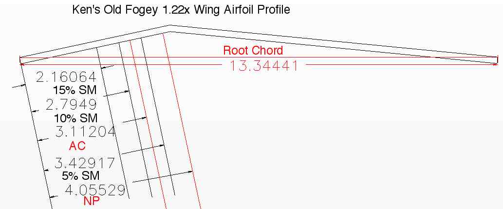 The CG reference lines were projected from the bottom of the wing root leading edge to the airfoil's apex for placement on the bottom of the wing. 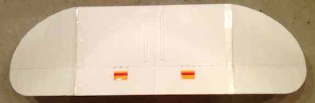 In the photo, the CG range is shown by the yellow band, ISCG range by the red band and the aircraft's NP is marked with black pinheads and is just slightly ahead of the airfoil's apex. For the maiden flight, the index fingers should be placed on the red band, and the bottom of the fuselage should be in the horizontal position. If anyone desires to make a version of the FliteTest Old Fogey, in any size, the following diagram shows the ISCG range as a percentage of the distance from the leading edge to the apex. 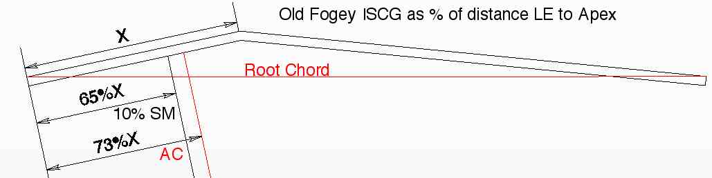 For the original FT Old Fogey, X = 3-1/2", 65%X = 2-1/4" and 73%X = 2-9/16". Ali Potter also questioned whether the angle of incidence, at about 3.80 to 3.90 was correct for this plane. The Angle of Incidence and the Decalage are not always the same, but on the Old Fogey, they happen to be. Decalage: The angle between the wing chord line and the stabiliser chord line is called the Decalage or Longitudinal Dihedral (LD).
Angle of Incidence: is the angle of a flying surface related to a common reference line drawn by the designer along the fuselage.
Keith Shaw, in his design talk to the EMFSO stated, "A plane flying in the 30 to 50 mph range, probably needs 2 degrees difference between the wing and the tail. For a plane in the 20 mph range, it could be 3 degrees. At 100 mph, you only need 1/2 degree or even none at all. I've seen gliders with 5 to 7 degrees. Why they have it, I have no idea." The original FT Old Fogey, and my enlarged version, spend most of their time in the 20 mph range. By Keith Shaw from his talk to the EMFSO 1992 Slightly edited for brevity and clarity by Ken Myers As the airplane gets close to its perfect center of gravity, the drag of the airplane drops dramatically, which means it takes less power to fly. Flying an abnormally nose heavy airplane, burns an extra 20% power just to counteract the nose heaviness. 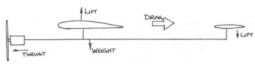 It's the old weight/lift/thrust/drag problem. Normally, an airfoil creates drag, but it also creates a pitching movement, which, with most airfoils, tries to push the nose down. Symmetrical airfoils glide beautifully. In a glide, a typical flat bottomed wing tries to do a half outside loop. To prevent this, something is usually done with the horizontal stabilizer. A lot of glider designs get carried away and stick the stabilizer on at a drastic leading edge down attitude. This acts like up elevator which lifts the nose. That's all well and good, but in order to get that to work, the center of gravity is fairly far forward, so that the airplane has a chance of flying. It becomes like a beam balance. The wing is creating lift and drag. The tail is also creating lift and drag, but the lift is all down. The wing is lifting the whole airplane, so that if there is a pound of lift pulling the tail down, the wing needs to lift an extra pound, which increases its drag. Reducing the downward lift at the tail to just a little downward lift, which you need to counteract the wing pitching moment, can get the center of gravity back further on the wing and get the beam balance equation to work more efficiently. The tail is creating less downward lift, therefore less drag. The wing doesn't have to lift as much, so its drag drops. The drag of the airplane becomes reasonable. An airplane with a lot of negative tail incidence, and the CG well forward, will glide at only one speed. If it goes any faster, it will try to loop. When the plane comes out of a stall, it will drop quite a ways before it recovers. First, set up the CG according to your plans. Then, there are several tests you can make, aerodynamically, to find out what your CG is like. These tests are based on the idea that the angle between the wing and the tail is reasonable. It sounds funny, but almost no matter what you do, the airplane will try to fly with the stab level. There are a few exceptions like biplanes. Assuming even semi-good wing and tail angles, a quick way of finding the optimal CG is to pull back to 1/2 throttle at altitude. Fly well above the minimum glide speed. Fly at 'cruising speed'. Make several passes up and down the field, at several hundred feet, playing with the elevator trim until the airplane flies level with no transmitter inputs. Leave the throttle alone, but force a 30 to 40 degree dive. When the plane has gained a 20% to 30% increase in speed, (say 50 ft. or so), so that it's accelerating, take your thumb off the stick. If the airplane continues on straight, (hopefully not for very long!), it's at the laterally perfect center of gravity. It is neutrally stable. Ideally, I shoot for something that is just slightly trying to pull up, slightly positively stable. If the stick is released, and the airplane tries to do a half loop, the airplane is very NOSE HEAVY. When the airplane picks up speed, the negative incidence, (or slight up elevator trim), acts like up elevator and will try to make the plane loop. (The increased speed makes the trim have more effect.) As the CG is moved back, there is less of a downward load on the tail, so speed has little or no effect. On the other had, if the airplane dives steeply, it's TAIL HEAVY. If the CG is well back, the tail actually has to provide positive lift to balance. When the airplane flies faster, the tail lifts more and the dive is increased. If the airplane always does a loop on the test, or has a 6 or 7 degree differential, put the CG further back, and reduce the difference to 3 to 4 degrees. That should add quite a bit of duration to the flight because of the reduced drag on the airplane. Old timers, with lifting stabs, often have the CG around 70%. My Zomby trims out at almost 70% of the chord from the leading edge. It's way back! 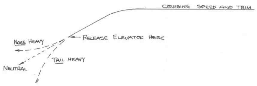 It's always best to get the stab incidence right rather than fiddle with the wing. There are many kits on the market that have the center of gravity in ridiculous spots and have incredible angles of attack. To the designers of these planes, if the plane flies, it's a good airplane. It really depends on what you want to do and what means something. If flying overhead with transparent covering is desired, then you can do anything. If super long flight times mean something, then that means efficiency. What the Chinese Don't Know
Many Chinese designers are tasked by American companies to supply them with aircraft designed to the American company's specifications. Unfortunately, the Chinese produce a design that meets the outer appearance of the requested design, but they are very poorly structured. If the Chinese designers took the time to review the excellent design practices outlined in "Building and Flying Electric Sport Scale, Transcript of Keith Shaw's presentation to the 1992 Electric Model Fliers of Southern Ontario General Membership Meeting, March 1992, Transcribed by Martin Irvine Kingston, Ont.", then there would be less landing gear failures, as well as other structural failures of the Chinese almost-ready-fly (ARF) balsa and plywood aircraft. My observations, over many decades, regarding ARF Chinese balsa/plywood type design, is that the Chinese have no idea what stress risers are or how to tie the airplane components together into a light, but strong, where it needs to be, structure. These points, and a great deal more, are in that document. The original, single document is in four parts on the Internet, and has been since January 1996. Recently, Patrick Surry combined all four parts into a single .pdf document. 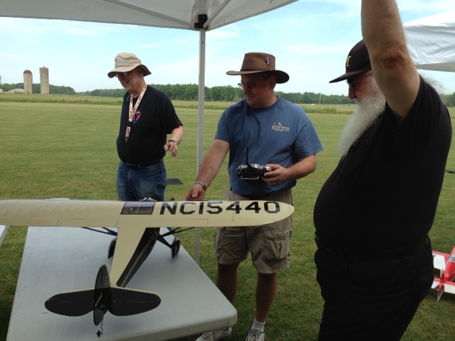
Keith Shaw (foreground), inspects Jim Young's self-designed Monocoupe 90A (center) as Roger Wilfong (background) looks on. 06/04/2016 Balsa Butcher's Flying Field, Quincy, MI
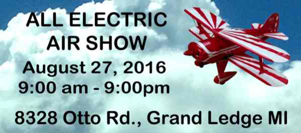
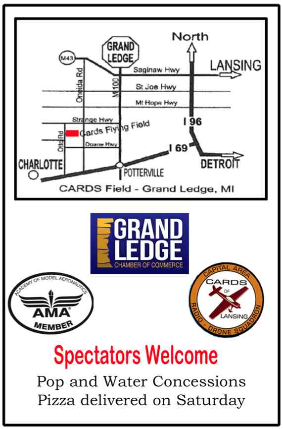
Upcoming CARDS Electric Fly-in On Saturday, August 27, the CARDS (Capital Area Radio Drone Squadron) present their 6th Annual Electric Fly-in from 9 a.m. to 9 p.m. The CARDS flying field is located at 8328 Otto Rd., Grand Ledge, MI, 48837. The event is open to all RC electric fliers that have proof of current AMA membership. Planes, multi-copters and helicopters are all welcome. The flying field features the best two runways in Mid-Michigan. The field will be available to registered pilots for electric only open flying on Friday, Aug. 26 from 3 p.m. to 9 p.m. There are pilot prizes and a raffle on Saturday. The landing fee is $15, which includes pilot pizza and soda. For more information contact the CD, Marv Thomson, phone 517-802-7675 or email Marv. There will be a pop and water concession.
Return to "What's In This Issue" To Reach Ken Myers, you can land mail to the address at the top of the page. My E-mail address is: KMyersEFO@theampeer.org |