|
Ampeer Paper Subscriber Reminder
When subscribing to or renewing the paper version of the Ampeer, please make the check payable to Ken Myers. We do not have a DBA for the Ampeer or EFO. Thanks, Ken
Keystone Indoor Electric Fly Article: URL Correction
Last month I mentioned the article by Bob Aberle about the KIEF event. John Worth, editor of RC Micro World/Cloud 9 RC, informed me that I had the URL for Bob's article incorrect.
I immediately changed the URL in the December issues, but some folks may have missed the update. The correct URL for Bob's article is www.cloud9rc.com/kief
John is providing this article FREE, so be sure to check out his site and seriously consider a subscription!
Return to "What's In This Issue"
Cubic Wing Loading
By Ken Myers
In the February 2009 Fly RC, Scott Stoops covered this topic in his "Primary Training" column, p.48. This is the first time I have seen this topic covered in the mainline modeling press in a long time, and I must add, it is about time! Thank you Scott for bringing it BACK into the general modeling publics' knowledge base.
I first became aware of Wing Cube Loading (AKA Cubic Wing Loading) in an article by Francis Reynolds published in the September 1989 Model Builder. The article included the history, range of loadings, displacement loading, electric power loading, a performance factor and much more. I have placed the original article online at www.theampeer.org/CWL/reynolds.htm
As Francis stated in the article, "Wing loading is a lousy way to compare models with each other and with full-scale airplanes, because wing loading varies with the size of the plane. The problem is that we are dividing weight, a cubic-like function (weight is proportional to volume which we measure in cubic feet) by area, a squared function measured in square feet. We should be, and many modelers are, comparing planes by their wing cube loading, which is independent of size because both the numerator and the denominator are cubic."
With that article as my introduction to the concept, I started using CWL as an indicator of an RC plane's "relative flyability".
As well as wing cube loading, Francis discusses a performance factor in his article. I didn't get it at the time, and even now, don't agree with it entirely.
In the June 1994 Model Builder, Roger Jaffe presented "Aircraft Performance Parameters Revisited." He references Francis Reynold's article and discusses his ideas about a performance factor. The most significant part of the article is that using the WCL (CWL) helped him to improve the predictive value of his Aircraft Performance Ratio. Again, this article reinforced my opinion of the CWL concept/theory. I have placed his article on the Web at www.theampeer.org/CWL/jaffe.htm.
While the performance factors mentioned in the above two articles seemed to make some sense in their day, they do not seem to apply today.
By 1997, I was a firm believer in the concept. In the December 1997 Model Airplane News, Larry Renger had an article titled "3D Wing Loadings: A Better Way to Scale Models and Compare Different Size Models Easily". In the article, Larry credits Ron St. Jean's article called "Wing Loading is Three Dimensional" published in the August 1959 Model Airplane News as his introduction to the concept.
Larry reinforced my belief that this theory really works, and works well. In his opening paragraph he states, "Wing loading, as generally used, is very limited in the range where any given loading is valid. There is a much better way to evaluate the weight of a model and compare it to others. really powerful theory will let you target the correct weight for a new model based on larger, smaller or different design models. Happily, such a theoretical solution exists and works well."
Larry's article is online at www.theampeer.org/CWL/larry.htm.
Unfortunately, all three articles fail to mention the simple, elegant formula for finding the CWL (AKA WCL).
CWL = weight in oz. / wing area (WA) in sq.ft. ^1.5
If you have a problem with that math, FlyRC has placed a real time calculator online for you to use.
www.flyrc.com/calculator.shtml
One interesting thing to note, when using this theory, is that there is a direct relationship between the Imperial and Metric numbers. If a CWL is 3.22 oz./cu.ft. it is also 3.22 Kg / cubic M. There is very, very little deviation between the two measuring systems. I�m not sure why that it is, and someone with some math knowledge might be able to help.
I have expanded the groupings of aircraft types mentioned in all the previous articles for a given CWL. My expansion is based on extensive data that I have collected for electrically power and internal combustion powered models. The data is available as an Excel spreadsheet and can be downloaded at
www.theampeer.org/M1-outrunners/metricnewtheory.xls
I have identified at least 7 levels, with a new level emerging as you read this. It is important to remember that on a relative scale, the lower the CWL the easier it is to fly. Also, the lower the level the more vulnerable it is the wind. As a general rule, higher level models handle the wind better than lower level models.
Level 0 - CWL ? - ?: This is the emerging area of indoor living room fliers. I only have data on one plane so far, but its CWL falls below the lowest Level 1 plane that I have recorded.
Level 1 - CWL ? - 2.99: Generally flown indoors in "large" areas such as gyms or larger venues or outside in extremely calm conditions. They generally have a maximum pitch speed of less than 25 mph with the average and median being about 22 mph/23 mph. They include some 3-D foam types, profile foam types and light structure film covered types. Some examples are the GWS Tiger Moth Slow Flyer, LightFlite RC Bug, E-Flite Jenny JN-4 Slow Flyer ARF and HL Profile scale foam 3D Gee Bee. I have tended to call these Indoor models, although that may change when more Level 0 data is collected.
Level 2 - CWL 3 - 4.99: The electrically powered version of these model types may be flown in large indoor venues or outdoors in very low wind conditions. They tend to have pitch speeds in the 35 mph to 40 mph range. A lot of the electrically powered 3-D type planes are found in this level. Some examples for the level include the E-Flite Ascent sailplane, Multiplex AcroMaster, Aeroworks Sukhoi 3D, Green RC Models USA Curtiss Jenny Bipe, SR Batteries Bantam Monoplane, Northeast Sailplanes Hyper2 ME sailplane and Fancy Foam Models Sukhoi SU-29.
I have recorded three internal combustion engine powered planes at this level. They include the Giant U-Can-Do 3D, Bruce Tharpe Engineering Delta Vortex and Kyosho Flip 3D 40. They have relative large wing areas, in the 900 sq.in. to 1800 sq.in. range. There median pitch speed is almost double that of the electrically powered versions in this level.
I have tended to call the electrically powered versions Backyard models, as they don't require much more maneuvering or flying room than a typical American baseball infield. Of course gliders must be excluded form the generality. With a median weight of 16.7 oz. for the electrically powered versions, the AMA would consider the vast majority of these planes Park Flyers.
Level 3 - CWL 5 - 6.99: The electric power versions in this group usually can be comfortably flown in an area about the size of a two soccer fields. Again, gliders require more room. They have a median pitch speed of about 55 mph. The majority of electrically powered 3-D type planes are found in this group. With a median weight of 26 oz./27 oz. more than half of the planes that I have collected data for would be considered Park Flyers by the AMA. Some examples of electrically powered Level 3 planes are the Precision Aerobatics Katana MD 3D, Great Planes ElectroStik RXR, Cermark Victor FlyRC (warm-liner), Tiger 400 ARF and GWS E-Starter.
The Level 3 internal combustion engine powered models have a median weight of 140 oz. with the median wing area being 1100 sq.in. Their median pitch speed is 55 mph, the same as the electrically powered versions. Because of their size and speed, all of them would require an RC club field for flying, yet they would be no more difficult to fly than the smaller electrically powered versions. Some examples are the Airborne Models Tamcat Trainer 40 ARF, Hangar 9 FuntanaX 100, Great Planes Big Stik 60 ARF, Billy Hell MOJO .40 3D, and RC Guys 33% Pitts S1 ARF bipe.
Level 4 - CWL 7.00 - 9.99: The vast majority of electrically powered and internal combustion powered RC planes are found in this CWL level.
The electrically powered versions have a median weight of about 30 oz. and median pitch speed of about 50 mph. They can be almost any type of plane, sport, sport scale, multi-engine, biplane, etc. Some examples are the E-Flite Piper Pawnee 15ARF, Parkzone T-28 RTF, Hanger 9 Edge 540 33%, Goldberg Senior Falcon ARF, and HL Flying Styro B-25 Mitchell.
The internal combustion powered models at this level tend to be quite a bit larger with a median wing area of 1168 sq.in. and median weight of 207 oz. (~13 lb.). The median pitch speed is a bit faster at 60 mph. The majority of internal combustion 3-D type planes are found at this level. Some examples are the Sig 33% Edge 540, Kondor Model Products Pitts Model 12 ARF bipe, Great Planes Ultimate Bipe ARF, Hanger 9 Pulse XT 40 and Sig Kadet LT-40 ARF w/floats.
Level 5 - CWL 10 - 12.99: No 3-D type planes are found at this level or higher.
The electrically powered versions have a median wing area of 460 sq.in. and median weight of about 70 oz. The median pitch speed is about 55 mph. They tend to fly very well in the wind. Some examples are the E-flite T-34 Mentor, ElectroFlying Fusion, Great Planes Seawind, E-Flite P-38 F-5E Lightning 400 ARF, and Miss America P-51 (Hangar 9 conversion).
The internal combustion engines planes at this level have a median pitch speed of about 65 mph, and again tend to be slightly larger and heavier than their electrically powered counterparts. Some examples are the Great Planes Super Sportster 40 MkII ARF FlyRC, Carl Goldberg Skylark 56 Mark II ARF, Hangar 9 F-22 Raptor PTS, Hobby Hangar OV-10 Bronco (twin) and the Goldberg Anniversary J-3 Cub on floats.
Level 6 - CWL 13 - 16.99: The majority of scale and multi-engine planes are found at this level. Both the electrically powered and glow powered versions have a median pitch speed of about 70 mph. These planes are demanding to fly and require the pilot's constant attention.
The electrically powered versions have a median wing area of 564 sq.in. and median weight of 107 oz. Some examples include the HL Graupner Nemesis Micro RC Scale Pylon Racer, Hangar 9 Corsair, E-flite DHC-2 Beaver w/floats, and Skyshark R/C Messerschmitt 109E.
The internal combustion powered versions have a median wing area of 721 sq.in. and median weight of 154 oz. Examples include; Hangar 9 B-25 Mitchell, Top Flite P51D Mustang, Kondor Model Products deHavilland Beaver w/floats, and Hangar 9 T-34 Mentor ARF.
Level 7 - CWL 17+: These are extremely demanding models to fly. The wing areas and weights for both the electrically powered and internal combustion engine powered planes are about the same for this group. Fortunately, only a very few model RC planes end up in this extremely difficult to fly and demanding level.
Electrically powered examples include a Hangar 9 B-25 Mitchell and Great Planes' Matt Chapman Authorized Cap 580.
Internal combustion powered examples include the Great Planes Seawind, Kondor Model Products Shorts Tucano T1, Skyshark R/C SBD Dauntless, Top Flite Cessna 310, and AK Models SU-27 Flanker.
I have reprinted the levels that FlyRC is using on their Web site so that you can compare it with my information from above.
Typical WCL Values for Models
Slow flyers and thermal gliders - under 4
Trainers, park flyers, 3D - 5 to 7
General sport and scale aerobatic - 7 to 10
Sport and scale models - 10 to 13
Warbirds and racers - 13 and over
As you can see, Scott and FlyRC have done their homework.
Scott did make one statement in his article that I cannot agree with. He said, "This month I review wing loading and introduce a new, and possibly more useful, performance prediction tool: wing cub loading (WCL)." It is clear from my references that this concept for model loadings goes back as far as 1959, so I would hardly describe it as "new", especially since I have been using it for about the last 20 years.
During the past couple of years, I have visited various local RC clubs with my presentation on the topic of Cubic Wing Loading (CWL AKA WCL). My next presentation will be at the Skymasters Radio Control Club of Michigan on Wednesday, January 28, 2009 at Larson Middle School. 2222 E. Long Lake Road, Troy at 7:00 PM. Everyone is welcome.
Return to "What's In This Issue"
Why Can't They?
Editorial By Ken Myers
I just renewed my FlyRC subscription for three more years this morning. That being said, why can't they get a decent proofreader? Month after month there are significant errors that get published in FlyRC. Believe me, I do understand about editing and proof reading. The Ampeer is far from error free, but even though I have contacted FlyRC many times about their errors, very little seems to be done about it.
The February '09 issue of FlyRC has a review of the Maxford Curtiss Jenny starting on p.104. (www.maxfordusa.com/gm-jenny-50-trans.aspx)
It is quite obvious that the reviewer, Steve Kessinger, made a HUGE mistake. He never measured the wing area! The SPECS box on p. 104 states that the top wingspan is 50 in. and the wing area is 364 sq.in. Folks, this is a Jenny! A Jenny is one of the most famous biplanes of all time. Picture it in your mind. Most of you can. Do you see the problem? At 364 sq.in. and with a 50 inch top span, I hope you�ve adjust the chord in your mind to toothpick size! Common sense screams that this can't be possible.
Besides not catching the supplier error, the author based his wing loading on the supplier's given area of 364 sq.in. That would give the plane a cubic wing loading (CWL) of almost 11 (Level 5), which once again indicates a HUGE error. It is extremely rare to find a biplane with a CWL of 11, especially this one when the author said, "... it's a perfect airplane for low-time pilots..." Level 5 models are not "perfect airplanes" for low time pilots.
I thought the model looked familiar and checked the December '08 issue of Model Aviation. The AtlantaHobby.com Curtiss Jenny is reviewed starting on p. 76. (www.atlantahobby.com/shopexd.asp?id=7076)
Using the two articles and the Web pages, I have concluded that these are the identical models provided by two different suppliers.
Both suppliers give the top wingspan as 50 inches and bottom wingspan as 40 inches and the length as 33 inches. Maxford USA states that the wing area is 364 sq.in. and Atlanta Hobby says it is 607 sq.in. The FlyRC reviewed plane weighed 44 oz. RTF while the plane in Model Aviation weighed 38 oz. Maxford USA says the flying weight is 34 oz. while Atlanta Hobby gives 36 oz. as the flying weight.
Using data from www.airventuremuseum.org and www.airminded.net/jenny/jn4_spec.html I came up with the following for the full scale Jenny.
Top wingspan: 43 ft. 7.375 in.
Bottom wingspan: 33 ft. 11.25 in.
Length: 27 ft. 4 in.
Top wing area: 203.14 sq.ft.
Bottom wing area: 149.42 sq.ft.
Total area: 352.56 sq.ft.
Weight empty: 1430 lb.
Gross weight: 1920 lb.
Gross wing loading: 87.13 oz./sq.ft.
Gross CWL: 4.64 oz./cu.ft. (Level 2)
Scaling for the model:
Top span: 523.375" (full-scale) / 50" (model) = 10.4675
Bottom span: 407.25" / 40" = 10.18125
Length: 328" / 33" = 9.9393939
From the above scaling, it is quite clear that this is not a scale model. The average "scale" is 1:10.2. Using 10.2, for the top wing area, to be a scale model, the area would be 1.9525183 sq.ft. or 281.16 sq.in. The area for the scale bottom wing should be 1.4361784 sq.ft. or 206.8 sq.in. for a total wing area of 488 sq.in. 488 sq.in. does not agree with either area given by the model suppliers. The designer has taken some "liberties" with the scale outline, and my guess is that the chord has been increased a bit from scale to make the wings easier to build and add to the "flyability" of the model.
Over the years I have found that "suppliers", as a group, do not supply the correct information about their models, while manufacturers do so a bit more often. I would recommend that "suppliers" actually unpack the models they are selling and measure them! I would also recommend that the reviewers actually take the extra few minutes to measure the model they are reviewing and add the word "measured" to their review specifications!
FlyRC also provides a "Minimum Flying Area&qot; as part of their specifications. The Maxford USA Jenny and the E-flite Pawnee on p. 116 of the February issue both use "Ballfield" as the definitive term for the minimum flying. All of the "ball fields" in my area are either in parks, are parks or located at schools. This indicates that the reviewed models should be "Park Flyers." I believe there are a lot of folks flying RC that are NOT AMA members, but the AMA has a Park Flyer definition; "Park Flyer models will weigh two pounds or less and be incapable of reaching speeds greater than 60 mph. They must be electric or rubber powered, or of any similar quiet means of propulsion. Models should be remotely controlled or flown with a control line, remain within the pilot's line of sight at all times, and always be flown safely by the operator."
Neither of these planes weighs less than two pounds; therefore I believe that the recommendation should be "RC Club Field". I am suggesting that recommendation anytime a reviewed model weighs more than two pounds. While this point can be easily argued, there needs to be a line drawn, and that would be an easy and consistent way to do it.
The Sig Four-Star 120 review on p. 68 of the same issue has some interesting and conspicuous errors. The SPECS area states that the prop on the Aviastar 1.50 2-stroke is a Master Airscrew 12x6. I doubt it very much. Using the photo of the plane in knife edge on p. 68 and p. 69 I estimated that the prop might be a 20-inch, but since the photo is at somewhat of an angle, it is difficult to say for sure, but I am sure that you would never use a 12x6 on a 150-size 2-stroke. It also states that the RPM is 10,800. Since the maximum RPM for the engine, as stated on the Sig Web site, is 11,000 RPM, I find this hard to believe, especially if the prop is in the 18 to 20 inch range. One other thing that confirms that the prop is not a Master Airscrew 12x6 is the photo on page p. 70 that clearly shows a Zinger prop.
FlyRC, I really enjoy your magazine a lot. To me, it is the best one "out there." Please try harder to not make so many glaring mistakes, please!
Return to "What's In This Issue"
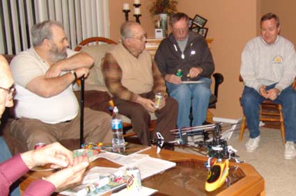
The December EFO Meeting
The December meeting was well attended and excellent. A lot of topics were covered and knowledge shared.
The meeting got rolling with Keith Shaw talking about his Phantom Fury. It is 50% larger than the original Comet kit that it is based on. It uses the same basic structure, but has metal landing gear and just a bit more structure in the rudder and elevator to allow sewn hinges to be added for RC control movements.
The wing features a unique "C" hold-down capture with small rare earth magnets holding the wing rearward.
The original plans were "blown up" from Keith's first Comet kit. It is a great trip down memory lane that flies excellently.
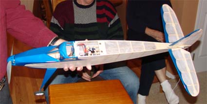
The crosspiece for the "C" capture can be seen just behind the blue covering to the top of the cabin area. The magnets are located at the top rear area of the cabin.
Joe Hass attended the meeting. He presented Keith with an original Comet Phantom Fury kit. How cool was that?
 Joe presents Keith with an original kit!

Both of the Furys
Joe also told us about the indoor flying that has gone on so far at the Ultimate Soccer Arenas in Pontiac. Several of the members have been attending the Tuesday sessions, and have also attended the session on the Saturday after Thanksgiving.
The indoor sessions at this great facility are on Tuesdays from 11 a.m. to 1 p.m. The Ultimate Soccer Arenas are located at 867 South Blvd., Pontiac, MI. A package of five sessions is $25. Spectators are welcome with NO admission charge. This is an unbelievably fantastic venue, and has to be seen to be believed.
For more information, you can contact Joe Hass at 248-321-7934 or visit the Skymasters Web site at skymasters.org.
Joe is also working on a POSSIBLE session for the Saturday after Christmas. (Two Confirmed - see Upcoming E-vents) Please check the Skymasters' Web site for confirmation of this possible flying day and times.
Dare I say, "Kid with a new toy"?
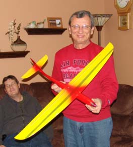
Rick Sawicki brought over his son's latest project. It is a SUNRACER II F5D PYLON RACER from Europe. While it may look to some to be just a "really neat, small model", this is one FAST little plane. With the custom wind NEU 1105/2.5Y 4000 Kv motor, 4.1x4.1 APC prop at 38,000 RPM, and a 3S Li-Po, it can reach speeds up to 145 mph! It should be an "interesting" flier.
Rick also brought over a couple of small outrunners that he wanted to determine the Kv of. One was supposedly a 3200Kv from United Hobbies/Hobby City/Hobby King and the other was from DONSRC and was called the DONS WICKED 2700.
While the members enjoyed some snacks, Ken and Rick went to the dungeon and took some readings for the two motors using Ken's drill press and voltmeter.
Jim Young was up next. He brought his T-Rex 450. It was a used machine that he'd picked up at a recent swap shop. He's been flying helicopters for a little while now, and wanted something a bit more advanced. He noted that while helicopters tend to be "money pits" but you can usually find reasonably priced parts on RC Groups. His new chopper is made up of parts he purchased at the swap shop, as well as online purchases.
Next Jim shared several of his plans for upcoming kits and projects. He has a new WACO YMF-5 coming off the drawing board with the laser cut parts already on order for the prototype. It is a larger version of his currently available model with a lot of nice, new features. The current version is here:
www.tnjmodels.rchomepage.com/tnjwaco.php
He also has the plans drawn for a smaller version of his Wedell-Williams Model 44. Photos of his large-scale version can be found here: www.tnjmodels.rchomepage.com/tnjgallery.php
His new pride and joy is going to be a 1/4-scale Brown Racer. He shared a lot of information and photos that he received from a person who worked on the restoration/recreation of the original.
He is drawing his own full-scale 3-view and then will reduce the 3-view to create his plans.
Super projects Jim!
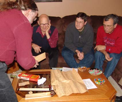
Bill Brown showed a wing panel for his Sig 1909 Antoinette. He wondered how to keep the panel from bowing when the covering was applied. Keith told that it probably wouldn't matter, as the wings flex a lot in flight on these types of planes.
Keith Shaw had picked up some Black and Decker VPX packs at a very good price while on a recent vacation. They were on clearance, as the VPX system has not taken off for Black and Decker. Keith demonstrated how to open the pack and harvest the two 1100mAh 18650 "A123" cells. He uses these cells in some of his smaller planes. They are the same chemistry as the 2300mAh "A123" cells, so they are very useful. The cells can also be found in the DEWALT DC9180 pack.
Ken put the information that he and Rick had collected on Rick's motors into a spreadsheet that Ken had created using information from Tom Cimato and determined the Kv of Rick's motors. The one that was supposed to have a Kv of 3200 turned out to be 3595 and the one that was supposed to be 2700 figured out to be 2794.
The Excel spreadsheet is available at: www.theampeer.org/Kv/Kv-Worksheet.xls
In the fall of 1989, Ken and his flying buddy, Jeff Hauser, put together a video called "Electric Flying in the '90s". The video used in its production was shot between 1986 and the summer of 1989. Ken showed the video complete with funky classical music and graphics created on an Apple IIGS. Some of the newer electric flyers were a bit amazed to see the performance that we had back in the "olden" days using Astro Flight motors and NiCads. They were also "amazed" and how much thinner Ken and Keith were, and how much darker their hair was.
The general meeting broke up about 10:30, but some folks stayed on to discuss more e-plane ideas for about another hour.
It was a great night. Thank goodness the Michigan winter weather had cooperated.
Return to "What's In This Issue"
Measuring Kv Using the Drill Press Method
As part of the December EFO meeting, Ken Myers showed the members how to measure brushless motors Kv (RPM/v) The math came via Tom Cimato of MaxCim Motors.
Kv
Kv is a motor constant and is directly related to Kt, the motor torque constant. Kv is most often expressed as RPM/Volt or RPM/v. Kt is often expressed in the units inch ounces per amp. Kv (expressed as RPM/v) * Kt = 1352.5. The Kv motor constant has nothing to do with the applied voltage. It is part of the motor's physical makeup.
Kv is also known as the generator constant or dynamo constant. When any electric motor is spun physically it generates electricity. It doesn't matter whether it is a brushed or brushless motor.
A typical hobby brushed motor can be spun by a drill press at a constant speed. By measuring the DC voltage across the terminals, with brushes set to neutral timing, and knowing the RPM of the drill press the Kv can be calculated. i.e. 1560 RPM / 1.6v DC measured volts = 975 RPM per volt. (To see how timing affects a motor, read my Timing Test.)
A brushless motor isn't quite as simple to do, but can be done using some math. A brushless motor has three possible lead combinations that need to be measured using AC voltage. i.e. Determine the constant drill press RPM (1560 in this example). Measure the AC voltage on each pair of leads, there are three possible combinations with a brushless motor. Lead combination A - 2.08, Lead combination B - 2.08, Lead combination C - 2.08. Note that most cheap motors do not have all three combinations come out exactly the same, but they do on the better quality motors. Use the average of the three voltage numbers if the measurements are slightly different.
Find the V-peak by multiplying the average AC volts by 1.414 In this example 2.08 * 1.414 = 2.94v
Divide 1000 (a constant) by the RPM (1560 in this case) = 0.64
Ke = V-peak ((2.94) * (in this case 0.64))/1000 = 0.00188
Find the inverse of Ke (1/Ke) (1/0.00188 in this case) = 531
Divide the inverse of Ke by 0.95 = 559 RPM/v or the approximate Kv expressed as RPM/v
Brushless Kv formula using drill press
Kv = (1 / ((Vac * 1.414) * (1000 / drill press rpm)) / 1000) / 0.95
Kt = 1352.4 / Kv
It should be noted that many manufacturers and suppliers, even the good ones, provide inaccurate information about the motor's Kv, so if you can, measure it to be sure you have the motor you want. Nothing really needs to be done to the motor to measure the Kv, so it should be easily returnable if the Kv is not suitable, as the shaft will only have been chucked into a drill press that is set up with a known RPM.
Advancing the timing on a brushed motor (using rotation of the brushes) or brushless motor (via an ESC setting) changes the apparent Kv, increases the RPM and Io (no load amp draw), increases the heat (wasted energy) more than neutral timing, but increases the power out.
Return to "What's In This Issue"
Switches For the Power Battery
I received an email from John Mrozinski inquiring about the use of switches for the power system.
Ken:
I think maybe I am finally starting to get a handle on all this electric jazz! Right now I have one little problem, I don't remember reading anything about it in any electric column I have read, or maybe I missed it!
I have an Ultra stick. I think it is the .60 and I was going to use an OS .91 four stroke but being as the plane is light, I decided to go electric with it. After carefully looking around for a motor. Being that the plane is less than 10 lbs, I got a KMS (Magnum) 4170/07 with a Phoenix 80 controller with 2 3 cell 11.1v 5000 mAh Li-Pos in series for 22.2 volts @ 5000 mAh.
I want to put a switch in the battery lead. I read somewhere that I would need a 100 amp switch. Then I was told that, no you don't need a switch that big, a regular switch would work fine as there is no load on it when you turn it on. This sort of makes sense to me! Perhaps this would be a good topic for the next Ampeer.
John Mrozinski
This is my reply to John:
Hi John,
The reason you've not read anything in the Ampeer about switches is that when using Li-Po batteries, you usually don't need or use one. Li-Pos must be charged outside the airframe. The usual procedure is to load the battery into the plane, but not connect it. When you are ready to fly, turn on your transmitter then the receiver and then connect the power battery. Button up the plane and go fly. After landing, disconnect the power battery, shut off the receiver battery and then the transmitter. Remove the Li-Po battery from the airframe.
That being said, this is, in my opinion, the most practical "switch" available.
Scroll to the bottom of the page and look for Arming Switch. www.maxxprod.com/mpi/mpi-21.html
Hope this helps,
Ken
John followed up with this email:
Ken:
Thanks a bunch. The reason I asked about that is that I figured that I would take my plane and battery pack to the field separately and then mount the battery when I got there. I just didn't want to keep taking the wing off to disconnect the battery.
The arming switch looks similar to what I came up with using Deans ultra plugs. Again thanks a bunch and I really enjoy reading the Ampeer.
John M

Photo from MPI Web site
Return to "What's In This Issue"
Why Can't They 2?
Joe Hass asked me to work up a different power system for the Hangar 9 Miss America. I looked at the recommended power system, and then I saw this at www.horizonhobby.com/ProdInfo/Files/EFLPower60OutrunnerInstructionsPDF.pdf
Prop: APC 15x10E
| Amps | Volts | Watts | Input
Watts/Pound | RPM |
| 56.0 | 21.3 | 1195 | 136 | 7375 |
Prop: APC 16x8E
| Amps | Volts | Watts | Input
Watts/Pound | RPM |
| 50.5 | 21.0 | 1060 | 165 | 6975 |
Notice that the Volts are approximately the same. The amp draw is higher for the 15x10E. Look at the RPM for each. Which one has the higher RPM? Which one should have the higher RPM?
Doesn't anyone every look at this stuff?!?
Just in case it doesn't strike you right off; with the same motor and the same applied voltage the higher the amp draw, the lower the RPM must be.
Based on 9700 RPM using the 13x8, the 4-stroke in the plane that Joe had flown has a pitch speed of about 73.5 mph and stall speed of about 17.3 mph yielding a pitch to stall speed ratio of about 4.24 to 1. That is very nice, as anything above a 4:1 ratio is excellent. I estimated the thrust for the 13x8 at 9700 RPM at about 128.33 oz., which gives it about 0.87 to 1 power to weight ratio with a full tank of fuel.
I then considered the limitations:
1. No larger than 15-inch diameter prop
2. No more than 10 "A123" cells (charger limitation)
3. Weight of the plane minus the engine, tank and throttle servo - about 116 oz. (that's minus about 20 oz.)
Using Drive Calculator (www.drivecalc.de) and my spreadsheet I looked at 6 possible power systems and gave Joe the information. He said that he wanted to use an E-flite Power 90. I refigured two conversions comparing the recommended Power 60 conversion to my two recommended Power 90 conversions.
HH Recommended Power 60 Conversion:
Motor: E-flite Power 60, TP Pro Lite 6S 6000mah, APC 15x10E
RTF weight: 140.8 oz.
CWL: 11.75 oz./cu.ft.
Pitch Speed: 62.1 mph Stall speed: 19.2 mph
Pitch to Stall speed ratio: 3.24
PF: 8.11
Watts in per pound: 135+
Conversion Using Power 90 and 8S1P Li-Po:
Motor: E-flite Power 90, TP Pro Lite 8S 5300mAh, APC 15x10E
RTF weight: 150.8 oz.
CWL: 12.59 oz./cu.ft.
Pitch Speed: 72.2 mph Stall speed: 19.9 mph
Pitch to Stall speed ratio: 3.64 (still very good)
PF: 12.91
Watts in per pound: 180
Conversion Using Power 90 and 10S1P "A123":
Motor: E-flite Power 90, 10S1P "A123", APC 15x10 pattern
RTF weight: 172.8 oz.
CWL: 14.42 oz./cu.ft.
Pitch Speed: 70.1 mph Stall speed: 21.3 mph
Pitch to Stall speed ratio: 3.30 (still very good)
PF: 8.72
Watts in per pound: 140+
With this information, Joe can now decided whether he wants to use a 4-stroke 100 or go with a Power 90 conversion.
Return to "What's In This Issue"
|

