 |
Flying High With Electric Power!
The Ampeer ON-LINE!
Fly the Future - Fly Electric! |
Site Table of Contents
| President: | Vice-President: | Secretary/Treasurer: |
| Ken Myers | Richard Utkan | Rick Sawicki |
| 1911 Bradshaw Ct. | 240 Cabinet | 5089 Ledgewood Ct. W. |
| Commerce Twp., MI 48390 | Milford, MI 48381 | Commerce Twp., MI 48382 |
| (248) 669-8124 | (248) 685-1705 | 248.685.7056 |
 | ||
| Board of Directors: | Board of Directors: | Ampeer Editor |
| David Stacer | Arthur Deane | Ken Myers |
| 16575 Brookland Blvd. | 21690 Bedford Dr. | 1911 Bradshaw Ct. |
| Northville, MI 48167 | Northville, MI 48167 | Commerce Twp., MI 48390 |
| 248.924.2324 | 248.348.2058 | 248.669.8124 |
| Mailed Ampeer printed subscriptions are no longer available.
The Ampeer is FREE on-line in Acrobat .pdf format and HTML with active links! | ||
| The Next Flying Meeting:
Date: Saturday, June 14 Time: 10 a.m. Place: Midwest RC Society 7 Mi. Rd. Flying Field | ||
| What's In This Issue? | ||||
| Part 2: An Initial Safe Center of Gravity (ISCG);
Using the Mean Aerodynamic Chord (MAC) and Aerodynamic Center (AC) Ken Myers continues his article on finding the initial safe center of gravity (ISCG). |
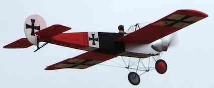
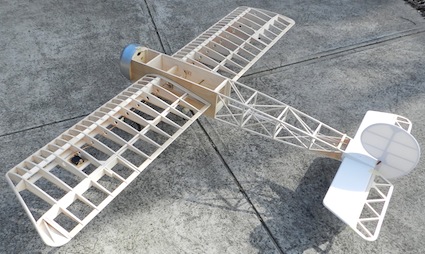
80" Span Eindecker David Hipperson shares information and photos on his build. | |||
| Upcoming Keith Shaw Birthday Party Electric Fly-in 2014 - Info and map for this upcoming event. | 30th Annual Mid-America Electric Flies 2014, links to the Flyer and map and hotel info for the 2014 Mid-Am. | |||
|
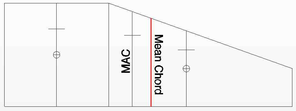
"Part 1 ended with the following: "The calculated semispan mean chord of the two panels was added by the author to Mr. Diehl's illustration and is shown in red. Note that the average mean chord of the semispan is NOT the MAC, according to Mr. Diehl. What happened?" On page 415 of Mr. Diehl's, he states, "There is a definite forward shift in the aerodynamic center of a wing due to the addition of a fuselage or of nacelles." He explained how to calculate the forward shift of the AC because of the influence of the fuselage and nacelles, when present. His calculations included the the placement of the wing on the fuselage, when referenced from the fuselage axis, as well as the length of the fuselage. For modeling purposes, his process is much too complicated. It is most important to note that there is a forward shift of the AC when a fuselage is added to a wing. The forward shift of the AC results in the actual MAC not being the semispan's mean chord. On page 418 of the report he also noted, "Failure to allow for this shift will lead the designer to locate the airplane center of gravity too far aft." A practical solution, that works for his illustration, should be good enough for a model aircraft. The illustration shows that the Aerodynamic Center (AC) has moved forward on the semispan's mean chord to a position that is 19.3% of the semispan's median chord. The result is that the actual Mean Aerodynamic Chord (MAC) is shifted towards the root chord for this example. The chord of the illustration's actual MAC becomes (mean chord-(mean chord*.193))/0.75, or (2.6654-(2.6654*0.193))/0.75=2.8679. The AC is 2.8679/4=0.717 on the MAC and the MAC's distance is 3.854" from the root chord, as measured on the CAD drawing. The AC shift is only part of the solution for deriving an ISCG. The horizontal stabilizer's area and the distance from the wing's AC to the horizontal stabilizer's AC, its tail moment, also influence the CG placement. The neutral point must also be taken into consideration. From previously quoted sources, "Placing CG 5% - 15% of MAC in front of NP creates a longitudinal (pitch) stability called Static Margin. A lower margin (tail heavy) produces less stability and greater elevator authority, while a higher margin (nose heavy) creates more stability and less elevator authority. Too high of a static margin results in elevator stall at take off and landing." Calculating the neutral point The Neutral Point as a percentage of the MAC = 0.25 + (0.25 * sqrt(sqrt(aspect ratio of the wing)) * (horizontal stabilizer area / wing area) * (Tail moment / MAC) It should be noted that the validity of the above formula could not be confirmed. All other references to the formula appear to be circular.
A second spreadsheet was created in the Excel workbook to allow for the AC shift to become 25% of the shifted MAC. Using Data from the spreadsheet for the shifted MAC, the CG formulas were reevaluated. |
|
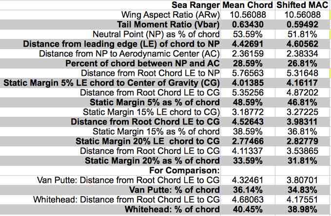
A table was created to compare the data for the Sea Ranger's semispan mean chord to the same data for the shifted MAC of the Sea Ranger. Data was included in the table to compare the Van Putte and Whitehead formulas. While a static margin of between 5% and 15% of the MAC was stated as 'typical' for CG placement, a static margin of 20% was added to the table for analytical purposes and to see if it might suggest a useable ISCG. The Van Putte result of 36.14% of the mean chord is a static margin of 17.44%. The Whitehead result of 40.45% of the mean chord is a static margin of 13.13%. The Van Putte result of 34.83% of the shifted MAC is a static margin of 16.98% The Whitehead results of 38.98% of the shifted MAC is a static margin of 12.84%. When the neutral point and static margins based on a percentage of the mean chord or shifted MAC are compared with the Van Putte and Whitehead formulas, the static margins appear to fall into the 'normal' range, but the the AC as a percentage of the mean or shifted MAC appears to be 'high' when compared to traditional percentages, 25% to 33%.
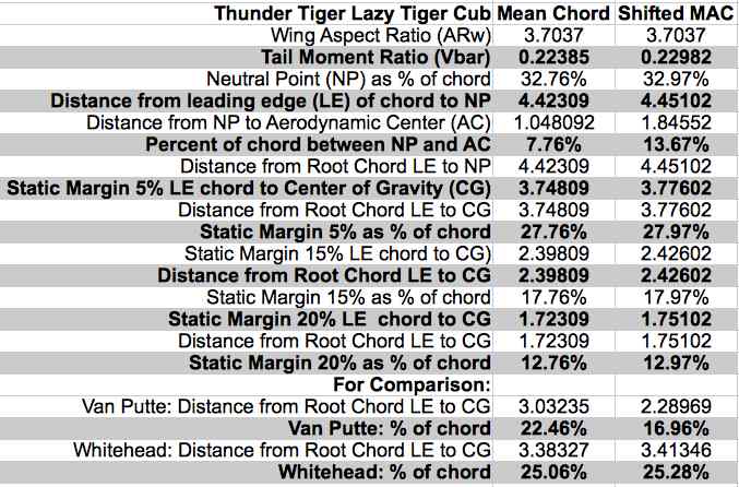
The Thunder Tiger Lazy Tiger Cub is a very atypical RC design. It has a low aspect ratio wing and a relatively short tail moment and low tail volume ratio. Before the first flight, the Lazy Tiger Cub's CG was checked and found to be near the manufacturer's rearmost suggested CG. It was at 3-3/4" from the wing's leading edge (LE) or 27.8% of the mean chord. According to the Thunder Tiger instruction manual, "Your Lazy Tiger Cub should balance 3-1/2" (26% of 13.5" chord) to 3-3/4" (28% of chord) back from the leading edge of the wing (about 3/8" in front of the main spar.)" At the time, that seemed to make sense as the percentage fell within the 'typical' range. The first flight did not go well. There were several 'issues' with the plane. One of the 'issues' was definitely the CG. It was extremely pitch sensitive and almost uncontrollable. A CG dive test was performed. The plane started a 1/2 outside loop during the dive test. The CG dive test indicated that it was extremely tail heavy. The CG Dive Test: How: (It is best to do this test on a close to windless day and into the wind. It must be performed so that observations can be made as to what is happening.) 1. Trim the plane for level flight at cruising speed
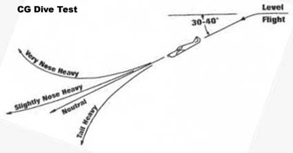 What the observations mean:
For more information on the CG Dive Test see Keith Shaw's "The Art of Low Power Aerobatics". To get the 'Cub' to fly well, and not be overly pitch sensitive, the CG was eventually moved to approximately 1-3/4" from the leading edge of the wing. It remains at that point and has been used as the "club" trainer for years. The CG position is approximately 13% of the mean chord. Required measurements for the spreadsheet input for the Lazy Tiger Cub. Wing:
Horizontal Stabilizer:
Wing Root Chord LE to Horizontal Stabilizer Root Chord LE: 23.875" |
|
A table was created for the Lazy Tiger Cub that compared the semispan's mean chord, semispan's shifted MAC, Van Putte's formula and Whitehead's formula. The table illustrates that using a static margin of 15%, for either the mean chord or shifted MAC, to select the ISCG for the Lazy Tiger Cub, the first flights would not have resulted in an overly pitch sensitive aircraft. It also indicates that when the Van Putte formula is used with the shifted MAC spreadsheet data, the recommended CG could also be an ISCG. The table also illustrates that the Whitehead formula does not provided a useful ISCG no matter whether the mean chord or shifted MAC data was used. |
|
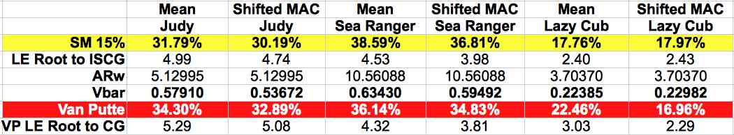
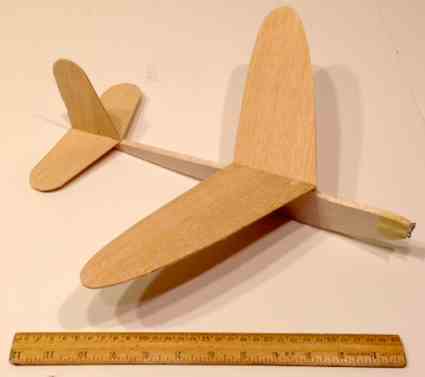
A table was created using the proposed Japanese 'Judy' bomber from Mr. Irving's article, the Sea Ranger and the Lazy Tiger Cub. The Whitehead formula was eliminated from table as his results do not appear useful in selecting an ISCG. All three planes are somewhat atypical. The Judy bomber has a trapezoidal semispan with a 'normal' range aspect ratio for this type of plane. It also has a trapezoidal horizontal stabilizer semispan with a fairly long tail moment yielding a relatively high tail volume ratio, Vbar. The Sea Ranger has two panels in the semispan. One is rectangular and the other trapezoidal. It has a relatively high aspect ratio for this type of plane. It also has a trapezoidal horizontal stabilizer semispan with a fairly long tail moment, again yielding a relatively high tail volume ratio, Vbar. The Thunder Tiger Lazy Tiger Cub has a 'low' aspect ratio, rectangular wing semispan, trapezoidal horizontal stabilizer semispan, comparatively short tail moment and very low Vbar. The actual flying CG of the Lazy Tiger Cub is 1.75". If the CG of the Lazy Tiger Cub is placed rearward or 2-3/8" from leading edge, it creates a plane that is extremely pitch sensitive and almost unflyable. Next, three actual models were used to verify ISCG calculations. MiG-17, 3 panel, swept wing and swept trapezoidal horizontal stabilizer, Jim Young, wingspan 28", Jim's proposed CG is 2.5" ahead of the trailing edge of the wing where it meets the fuselage - model not flown at this time
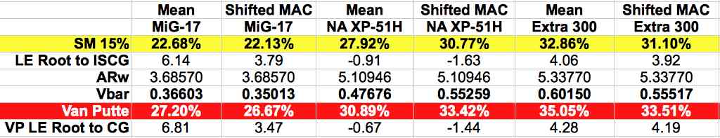
Their recommended CG is shown on page 18 of manual and coverts to about 4-3/8" measured on the root chord ahead of the trailing edge for Jim's version. That's an odd way to put it, but for this model, using a reference point noted as ahead of the trailing edge works out well. North American XP-51H forward swept wing and trapezoidal horizontal stabilizer, Mark Rittinger, wingspan 36", Mark's CG was noted as 2" in front of the leading edge at the wing root leading edge - model flown successfully E-flite Extra 300 32e trapezoidal wing and horizontal stabilizer, Arthur Deane, wingspan 52.5", supplier recommended CG 3.5 - 3.875 in. back from LE closest to the fuse A CAD drawing of an EXTRA 300, dimensioned to the E-flite wingspan, showed that for both the mean chord and shifted MAC for the E-flite Extra 300 a static margin of 15% fell within E-flite's suggested CG range. The Van Putte formula, using the shifted MAC data, provided a CG recommendation that fell only slightly, less than 1/8", to the rear of the recommended CG range by E-flite. Both the MiG-17 and the proposed North American XP-51H have swept wings. The MiG's is a typical rearward sweep and the proposed XP-51H had a proposed forward sweep. A CAD drawing of a MiG-17 was created. Both Jim's initial CG and the RC Lander recommended CG, scaled to Jim's 28" span, were noted on the drawing. The mean chord and shifted MAC were calculated using the spreadsheet. |
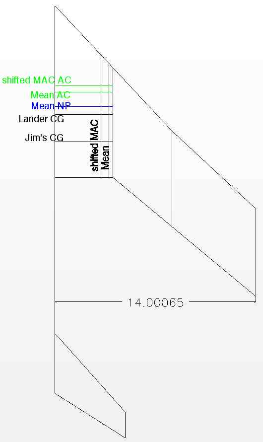
The results were unexpected. The mean chord's neutral point (NP) was calculated to be ahead of the Lander and Jim's initial CG estimation. To verify if something had gone wrong with the spreadsheet, the data was placed into the online calculator at adamone.rchomepage.com/cg3_calc.htm. Using a Static Margin (SM) of 15% the calculator showed a Mean Chord of 7.94", which was the same as the spreadsheet. The calculator calculated a NP slightly farther forward than the spreadsheet for the mean chord. In post #54 of Mark Rittinger's build thread for his North American XP-51H he noted, "I made a 1/16 balsa glider to double check my CG calcs." 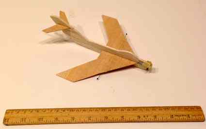 A reduced size glider of a MiG-17 was built using 1/8" balsa for the fuselage and 1/16" balsa for the wing and horizontal tail. The CG was adjusted using various size screws taped to the front of the fuselage. The initial CG was set at the AC suggest by the CAD drawing. The glider nosed into the ground after a very brief glide. The mean chord, and therefore the shifted MAC were NOT a very good ISCG as the glider was too nose heavy. Adjustments were made to the CG to find the "best glide" without the model "pitching up" or "nosing in." The best "downhill" glide was found to be when the CG was located between 7/8" and 1" from the center section trailing edge. On the glider, the Lander recommended CG is located about 1" in front of the trailing edge. A new formula was created and inserted into the shifted MAC spreadsheet to emulate the data found using the MiG-17 glider. To verify the swept wing formula, a second swept wing glider was built using the plans from the July, 1934 Universal Model Airplane News.
 The model was built full size with a span of 15-1/8". A static margin of 15% of the reformulated shifted MAC spreadsheet provided an excellent "downhill" gliding CG, which was 3/4" behind the CG shown on the plans. When flown with the CG as marked on the plans, the plane was noticeably 'nose heavy'. 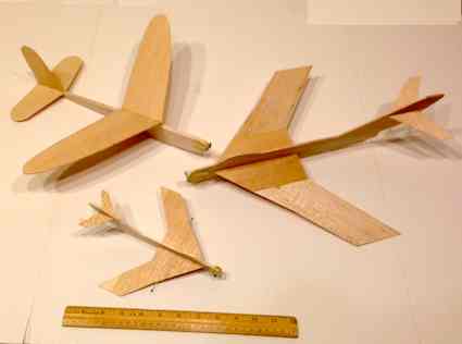
All three gliders A double-size MiG-17 glider was created. The ISCG was calculated using the reformulated shifted MAC spreadsheet with a 15% static margin. The CG on the larger MiG-17 glider was adjusted to the recommended 15% static margin point. From the first toss, the glide was as expected. |
A table was created to evaluate the ISCG for the three existing models. The dimensions were based on Internet 3-views and the wingspans stated by the designer or supplier.
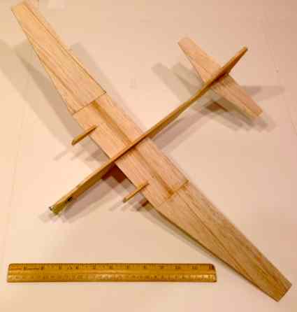 As a final test for the shifted MAC spreadsheet, I used a 3-view of the Boeing Sea Ranger to create a 24.75" glider of the Sea Ranger. The glider was balanced using a 15% static margin at 1-3/16" behind the root leading edge, as suggested by the shifted MAC spreadsheet. The first toss across the basement was a nice 'downhill' glide. Just what I was looking for! David's model data for the Sea Ranger was reentered into the shifted MAC spreadsheet. He stated that he had decided to use 3.6" from the root leading edge as his initial CG. The shifted MAC spreadsheet noted the CG was at 3.5" from the leading edge of the root chord when using a 20% static margin and 4" from the root chord leading edge when a 15% static margin was used. It looks like David's 3.6 inches from the root rib's leading edge falls within the range (15% to 20% static margin using the shifted MAC) for an initial safe CG. With the CG usually marked on the plans or noted in the construction or assembly manual, why did I feel that it was necessary to devote two issues of the Ampeer to this topic? In the January 2004 Ampeer, Keith Shaw noted, "There are many kits on the market that have the center of gravity in ridiculous spots and have incredible angles of attack. To them, if the plane flies, it's a good airplane. It really depends on what you want to do and what means something. If flying overhead with transparent covering is desired, then you can do anything. If super long flight times mean something, then that means efficiency." In 2011, the Super Tiger Lazy Tiger Cub turned out to be the type of plane Keith was talking about. The first flight of that simple design almost ended as the last flight of that simple design because the recommended CG range was very wrong, and I was not knowledgable enough about CG to realize it. Over the years I've run into several other airframes with quite 'uncomfortable' rearward CG recommended ranges by the manufacturer or supplier. Most recently they have included the parkzone T-28, E-Flite PT-17 and Maxford Antonov An-2. Luckily, the initial flights with them were successful enough to allow the CG to be tweaked to the pilot's ability and expectations as well as the plane's mission. One way to do that tweaking, and the explanation for it, is in the previously noted Keith Shaw article in the January 2004 Ampeer. Besides getting the CG right, it is important to have a good design based on solid aerodynamic principles. The following are references for information regarding Reynolds Number, span efficiency and the Oswald's efficiency factor.
If for some reason all of this math is too much for you, and you suspect that the recommended CG range might not be correct, take the time to make a glider of the model and give it a try. Let's get that CG right BEFORE the first flight! 80" Span Eindecker
I had been working for a while on a self-designed sport scale Curtiss Jenny but the urge came for a change just to provide a break. Two things gave impetus in that one, I had a set of plans for the Balsa USA 80 inch span Eindecker and two, a photo of an Eindecker replica in a copy of "Fighter Aircraft in Colour" by Bill Gunston. This aircraft was, apparently, used for movie work and has the advantages of having both ailerons as well as conventional tail and elevators. No criticism of the Balsa USA version, which I'm sure is great but I wanted to make some changes. Among these were a lighter structure, two piece wings with working rigging, an all moving rudder together with a more realistic undercarriage and tail skid. This meant it was worth re-drawing the plans but I kept the wing section along with much of that structure plus the stock tailplane. I aimed for an all up weight of eight pounds and felt that if I achieved that 5S would be more than sufficient. As a motor I chose the OS 5020-490 and I mated this to a Turnigy 16 X 7 wooden prop. The ESC is a Hyperion Titan 80 amp OPTO which is not really needed but I have several and the keep the ESC cool under the worst of conditions. The packs are two 5S 3200 in parallel and it seems as if I use about 20 Đ 25amps under normal flight. These two packs balanced the aircraft exactly without resorting to any lead which was a bonus. The structure went together very easily and the photos may show how basic it all is. Mostly it is 1/4" square balsa, balsa sheet and various thicknesses of ply. The joiners for the wings consisted of a very robust spruce main spar plus a 3/16 K&S wire rod plus matching brass tube to the rear. All of the rigging is via 60 pound coated fishing trace matched up with Du-Bro quick links. The cowl came from an old aluminum kettle and aluminum self adhesive 2" wide tape was used to cover the area between the cowl and cockpit. The Spandau gun from Williams Bros was a dummy on the original too. Mine was sprayed with dark grey metallic with licks of black. Covering is entirely white Oratex (Protex) which was then brush painted using artist acrylic. The 'red' is a home mixed match to the photo being mainly red and yellow to produce a very 'orangy' red. All of the markings are just hand drawn using either brush or felt tip pens. Finally an aerosol can of satin fixer was sprayed over the whole thing which gave a perfect (to me) colour and look to the entire airframe. As it happened the Eindecker turned out at less than 8 pounds and so in flight it is a real treat. If wished it happily flies comfortably on ailerons and elevator and that big, all moving, rudder is mighty powerful which is great for stall turns (hammer heads). I made a minor mistake during one take off where I'd inadvertently clicked into full rate on the rudder and for a moment or two it was more than a bit squirrely but I got away with it. Landing is a cinch and is just a matter of aiming it in the right direction while keeping a little throttle on to overcome the drag which is surprisingly high. I have to be honest and say I'm still getting used to it but I like it better every time I take the Eindecker out. So far I haven't needed to put in a single click of trim so something must have worked. If any one has any questions I've missed I can be contacted via Ken Myers and I thank him for this newsletter and letting me put in my latest piece. Regards
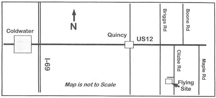
 Upcoming Keith Shaw Birthday Party Electric Fly-in 2014 The Balsa Butchers will once again be hosting the "Keith Shaw Birthday Party Electric Fly-In" at their field near Coldwater, MI. The event will take place on May 31 and June 1, 2014. Contest Director: Dave Grife - E-mail: grifesd@yahoo.com or Phone: 517.279.8445
The Flying Field will be open Friday, May 30 for early arrivals Saturday, May 31, hours are from 9 a.m. 'til 5 p.m.
Landing Fee is $15 for the weekend. Directions: Quincy is approximately 4.5 miles east of I-69. Clizbe Road is approximately 1.6 miles east of Quincy. The Flying site is approximately 1.5 miles south of US-12 on the west side of Clizbe Road. |
|
Announcing the 30th Annual Mid-America Electric Flies Saturday, July 12 & Sunday, July 13
Here are the links to the 2014 Flyer as well as the field map and local area hotels list. 2014 Map to the flying field and local hotels listing |
To Reach Ken Myers, you can land mail to the address at the top of the page. My E-mail address is: KMyersEFO@theampeer.org