 |
Flying High With Electric Power!
The Ampeer ON-LINE!
Fly the Future - Fly Electric! |
Site Table of Contents
| President: | Vice-President: | Secretary/Treasurer: |
| Ken Myers | Richard Utkan | Rick Sawicki |
| 1911 Bradshaw Ct. | 240 Cabinet | 5089 Ledgewood Ct. W. |
| Commerce Twp., MI 48390 | Milford, MI 48381 | Commerce Twp., MI 48382 |
| (248) 669-8124 | (248) 685-1705 | 248.685.7056 |
 | ||
| Board of Directors: | Board of Directors: | Ampeer Editor |
| David Stacer | Arthur Deane | Ken Myers |
| 16575 Brookland Blvd. | 21690 Bedford Dr. | 1911 Bradshaw Ct. |
| Northville, MI 48167 | Northville, MI 48167 | Commerce Twp., MI 48390 |
| 248.924.2324 | 248.348.2058 | 248.669.8124 |
| Mailed Ampeer printed subscriptions are no longer available.
The Ampeer is FREE on-line in Acrobat .pdf format and HTML with active links! | ||
| The Next Meeting:
Date: Wednesday, January xx Time: 7:30 p.m. Place: Ken Myers' house, Commerce Twp., MI | ||
| What's In This Issue? | ||||
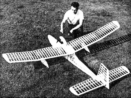
| Custom Privateer, Ken makes suggestions on powering this plane. | Some Nice Motor Mounts, Mike Russell shares a source for some nice motor mounts. | |||
| More on "A123" Toughness and a Little Complaint About Invasion Stripes on EVERY Model, John Bell shares his experience with "A123" cells and shares his feelings on Invasioin Stripes. |
Replacements for AF 15G Motors in a Bell YFM-1A, David Plummer is seeking a replacement for the Astro Flight 15. | |||
| A Note from Canada, Art Lane shares thoughts on several topics. | Regarding the October 2012 Ampeer and Batteries, Willie McMath shares his thoughts on batteries. | |||
| Electric Motor Kv or RPM/volt, Ken describes what Kv is and how to derive it several ways, as well as other motor "constants". | Hobby King/AEO Tech PO Wattmeter, James Frolik describes his experiences with this power meter/wattmeter. | |||
| Some Recommended Winter Reading, Ken recommends some articles to digest this winter. | ||||
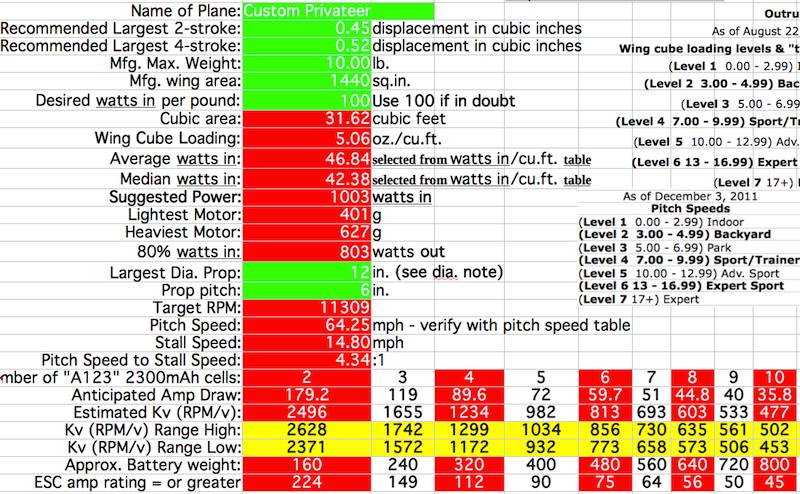
Screen capture of worksheet
|
Looks like you've lucked out here in several ways. About 1000 watts in looks good. A 10S1P "A123" 2300mAh pack looks about right, current-wise (36.8 amps) when using a 12x6 prop. I checked the Innov8tive Design page for the Cobra line of motors because Lucien has tested this brand with Master Airscrew 3-blade props. I found the Cobra C-4130-14 (5062-450, 400g) motor. That motor should work very well with a 10S "A123" 2300mAh pack and a 12x6 prop, either an APC 12x6E or Master Airscrew 12x6x3. Here's the specification sheet. The Web page indicates that using this motor and a Master Airscrew 12x6x3 3-blade prop the specs are: 29.6v (that is just a bit more than would be expected for a 10S "A123" 2300 mAh pack at 35 amps)
Please remember that the Cobra numbers come from actual tests run by Lucien Miller. Since you mentioned other motors, here are some similar ones to the Cobra, so performance should be quite similar as well. Scorpion S-4035-460 (5063-460, 435g)
I looked at MVVS, but didn't find anything that seemed to me that it would work, but I am not at all familiar with this line of motors. Others I found using http://www.rc-book.com Hacker A50-12S (4872-492, 389g)
The ESC should be one that is rated at 45-amps or greater. Good luck with your project,
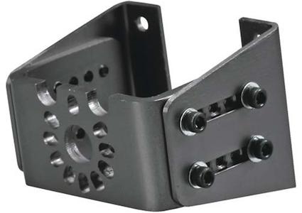
And a follow-up from Ned Thank you so much. It looks as if the DEWALT pack was just made for this application. Take off the top and solder leads onto the plus and minus ends of the battery circuit. I had been figuring about 750 watts in for sport flying a ten pound aircraft, but it looks as if going to 1000 watts will cost almost no weight increase at all, given that it is ballast or battery up in the bow. I have never flown anything close to 10S, but I suppose that as long as it is within spec for the motor and speed control, it should work out just fine. You have also even given me a source for a twelve inch three blade prop. I will hope to send you a picture of her on the water this spring. Some Nice Motor Mounts
Mike sent along the numbers for these nice motor mounts from Tower Hobbies. I had a chance to use the 40-size on a Sig LT-40 conversion this past fall. It really made the conversion super simple. Small LXLCL3, Length: 1.65" (42mm), Width: 1.97" (50mm), Height: 1.44" (36.7mm), Weight: 1.2oz (35g), Mounting hole dimensions 1.19"x1.19" (30.2x30.2mm) Medium LXLCL4, Length: 2.53" (64mm), Width: 2.18" (55mm), Height: 2.18" (55mm), Weight: 2.3oz (81g), Mounting hole dimensions: 1.325" x 1.325" (33.65 x 33.65mm) Large LXLCL5, Length: 3.59" (91mm), Width: 3.11" (79mm), Height: 2.17" (55.1mm), Weight: 4.9oz (140g), Mounting hole dimensions:1.85"x 1.85" (46.9x46.9mm) Extra Large LXMVU6, Length: 3.56" (90.5mm), Width: 3.09" (18.5mm), Height: 2.56" (90.5mm), Weight: 5.1oz (145g), Mounting hole dimensions:1.94"x1.94"(49.3x49.3mm) More on "A123" Toughness Hi Ken: My friend Andy Telzer and I have been flying A123 cells for about 5 years. We are still using the original packs and have not lost a cell to anything but "Finger Trouble". All I can say about them is that they are "Bulletproof". But to my pet bitch: almost every time I see some WW2 airplane (Spit in your latest Issue) I see both "Invasion Stripes--and Red"!! It would seem that every WW2 Aircraft had Invasion Stripes--DC-3s. Spitfires, Mustangs. B25s B26s etc--ad infinitum. While it is true, that on June 4th 1944, they were used to identify Allied Aircraft for the Normandy Invasion, following D-Day, the invasion stripes made Allied aircraft easy targets for the enemy. In late June 1944, some crews started removing the stripes on the upper surfaces of their aircraft. Stripes on wings were, per orders, to be removed between 25 August and 10 September 1944. On 6 December an order was issued to remove all invasion stripes by the end of the year. The actual period of the war that these were used was quite short (Germans were not stupid) and to have every model in Christendom sporting them, is ridiculous. Rant over--keep up the good work, John Bell
How true! They do add a bit of 'punch' to a model though. KM Replacements for AF 15G Motors in a Bell YFM-1A
I couldn't come up with a suggestion for David. Can some Ampeer readers help?
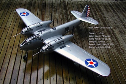 Hi Ken! I'm finally getting around to trying to fly my model of the Bell YFM-1A; it weighs about 10 lb. and I built it with a couple of AF 15Gs. I'm thinking it might be sensible to upgrade the motors to some brushless geared motors: do you have any suggestions for a candidate replacement (or two)? David Plummer
A Note from Canada
Mornin Ken, Gee, Cliff Tacey? (October 2012 Ampeer email from Cliff about the PT-19 power system. KM) It's been a long time since I heard or saw anything of him. He's still at it eh? I remember one of the Scale EventsĘin Michigan, quite a while back. I had my Sig Clipped wing Cub there with the OS 120 FS and Cliff helped me get it set up, after a thorough safety inspection. That was a memorable weekend. And, you are to be congratulated on your induction to AMA's Hall of Fame.... GREAT! (late as I am, Congrats!) We, Forest City Flyers of London, have just finished our "Special" Fall fun fly. Two of our oldest members were awarded the prestigious MAAC "Pioneer" award for service over the many years they have been members, Ted Buck, MAAC # 85 and Archie Steels, MAAC # 73. 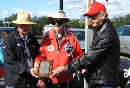 I've attached a picture of Archie receiving the award from our MAAC President, Ron Dodds, who flew in from B.C.Ęto make this presentation. Ted taught me how to fly, back in the late 70's and I've looked up to him ever since. Unfortunately, Ted couldn't join us, his health is not good. My article on the Sbach, which I call "Pumpkin Pimples" is fantastic. You can't see the "Pimples" on it in those pictures, Thanks. I'm now on flight #12 and it's becoming one of my favorite "Foamie" flyers. An amazingly BIG foamie flyer. The article on our Indoor BMO flying, again, thanks. We have a new indoor site for the upcoming season of indoor RC. It's at a place I used when I first started indoor programs, the Fanshawe College gym. It is a biggie, but not as big as the BMO center. It's the size of two basket ball courts with a 22' ceiling. It cost us much less, 50 bucks per hour. Yes, summer is almost over, and indoor is now taking it's place. That means back to the smaller stuff, but keeps my fingers nimble while I'm waiting for that first day next spring. Many thanks for the Ampeer again. I do enjoy reading this "Complete" newsletter. Regards
Regarding the October 2012 Ampeer and Batteries
Hello Ken, Just read the latest issue (October 2012 KM). I found a lot of useful information in it. I am learning a lot about LiPo batteries and A123s. I'm putting LiPos in my Loving Love and putting balancing plugs on everything that is motorized. So far I have not found the need for the receiver battery. I've enjoyed all of your issues. Keep them coming. I have a Top Flite Bearcat. It is a .60-size that was given to me. It is a kit built version from 27 years ago. I am putting a NTM 42-58-500kv on it and using a 6S1P "A123" 2300mAh pack. I will send some pictures later. Willie McMath By Ken Myers Ampeer Articles Regarding Motor Kv Finding R and K, December 1989 Motor Kv Question, January 2005 Measuring Kv Using the Drill Press Method, January 2009 It Is Not Just the Kv, May 2009 Ke variation, November 2010 (note: not a typing error; Ke is related to Kv) Identifying the Usefulness of an Unknown Brushless Outrunner, October 2011
Kv is a motor constant and is directly related to Kt, the motor torque constant. Kv is most often expressed as RPM/Volt or RPM/v. Kt is often expressed in the units inch ounces per amp. Kv (expressed as RPM/v) * Kt = 1352. (Note: Some sources uses 1355 as the constant.) The Kv motor constant is part of the motor's physical makeup. The voltage used to multiply the Kv constant by, to determine the RPM, is NOT the input voltage at the motor, for a brushed motor, or the input voltage at the Electronic Speed Control (ESC) for a brushless motor. There is a voltage drop from the input voltage. It is caused by the resistance of the motor. For brushless motors, there is an additional voltage drop caused by the resistance of the ESC. The net voltage (Vnet) equals the input voltage (Vin) minus the current times the resistance (the voltage drop). also Vnet = RPM / Kv Rm is a term that was used with brushed motors. It meant the motor resistance. The term Rm, as used here, means the motor resistance plus the ESC resistance, so that it may apply equally to brushed and brushless systems. Two data points are required to determine the Rm and Kv of a motor. The data points are gathered using a power meter (aka watt meter) and tachometer. Either an optical tachometer or phase tachometer will work. An accurate phase tachometer is much easier to use. All measurements are taken at FULL THROTTLE! Do NOT use partial throttle readings! Data should be gathered as quickly and accurately as possible. The motor should not be run for any extended period of time, ever! One of the earliest iterations of this method was presented in the December 1989 Ampeer. Unfortunately, I didn't really understand the concept and math at the time, but THE electric columnists, Bob Kopski and Mitch Poling, did. Data Points 1
Data Points 2
The math is completed using the Excel workbook spreadsheet titled Rm.
The Io (no load current) is also a valuable constant. Measure the volts and amps using a power meter with no propeller attached to the motor. For a no load test to calculate the Io, it is best to use a battery or power supply that applies only about 80% of the voltage that the motor is expected to run at. DO NOT ATTEMPT TO CONTROL THE VOLTAGE USING AN ESC! Getting the measurement at 80% of the expected voltage is sometimes difficult to do. If that cannot be done, just use the pack that has been used to do the Rm testing, but don't recharge it, unless it is extremely low. A major problem with many suppliers' is that they give an Io without noting the voltage. Io varies somewhat with the volts applied. This causes a problem when the Io is used to estimate 'iron loss' in the power out formula. Power Out Formula
While called constants, the Rm and Io are not truly constant. They vary slightly with the applied voltage. It is important to note that the Rm derived in the following examples is NOT the Rm that is often provided by the suppliers. Cobra C2203/52, wt. 17.5g
Results from spreadsheet:
The maximum amp draw is given as 7 amps. 80% of the maximum is 5.6 amps. On the Innov8tive Designs' prop test table the APC 7x5SF draws 5.6 amps.
The Io is used to calculate the Pout in watts.
Cobra C4130/14, wt. 400g
Results from spreadsheet:
The maximum amp draw is given as 60 amps. 80% of the maximum is 48 amps. 46.04 amps is used for the example as the measured APC 12x8E draws 46.04 amps at 29.6v.
The Io is used to calculate the Pout in watts.
The examples chosen were not arbitrary. They demonstrate some general trends that can be applied to all motors. 'Smaller, lighter' motors have a higher Rm than 'larger, heavier' motors and therefore a higher voltage drop. In general, for the way that they are used, 'Smaller, lighter' motors have a lower efficiency than 'larger, heavier' motors. One thing that was not demonstrated by the examples is that the highest Kv motor in a series will be the most efficient and have a lower Rm. Why? A higher Kv is created by using larger diameter wire for the windings compared to a lower Kv version of the same series motor with the same type of termination. Not all suppliers provided different Kv motors of the same 'size'. The Cobra C2203/34, which is in the same series of motors as the first example, has a Rm of 0.2255ohms (about 1/2 the resistance of the /52) for a voltage drop of 1.55V at 6.89 amp yielding 5.85Vnet. (Shown in the Examples on the Rm spreadsheet). At 6.89 amps the Vout is 79% of the Vin and the efficiency is about 72.6%. The /52 is a 52-wind and /34 is a 34-wind. The fewer winds of larger gauge wire on the /34 means that it has a lower resistance and higher Kv than the /52. One of the results of the previous testing method is the Kv. Another way to derive the Kv is with a phase tachometer and voltage measurement. An optical tachometer cannot be used for this measurement as the motor needs to be 'unloaded'. The Emeter II with the RDU or MDU and the phase tach lead can be used or a device like the AEO Tech KV Meter K0. The motor is run with no load, while the voltage and rpm are recorded. While not the 'true' Kv, it is close enough. For this type of measurement, RPM / volts = Kv.
Kv is also known as the generator constant or dynamo constant. When any electric motor's shaft is physically spun, it generates electricity. It doesn't matter whether it is a brushed or brushless motor. A typical hobby brushed motor can be spun by a drill press at a constant speed. By measuring the DC voltage across the terminals, with brushes set to neutral timing, and knowing the RPM of the drill press, the Kv can be calculated. i.e. 1560 RPM / 1.6v DC measured volts = 975 RPM per volt. (To see how timing affects a motor, read Timing Test.) A brushless motor isn't quite as simple to test. A bit of math is required. A brushless motor has three possible lead combinations that need to be measured using AC voltage. First, determine the constant drill press RPM (1560 in this example).
Find the V-peak by multiplying the average AC volts by 1.414 In this example 2.08 * 1.414 = 2.94v
Brushless Kv formula using drill press
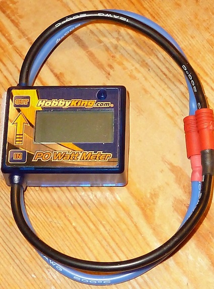
The Kv Spreadsheet (sheet Kv) can do the math for you. It should be noted that many manufacturers/suppliers, even the good ones, provide inaccurate information about the motor's Kv, so if you can, measure it to be sure you have the motor you want. Using this method, nothing really needs to be done to the motor to measure the Kv, so it should be easily returnable if the Kv is not suitable, as the shaft will only have been chucked into a drill press that is set up with a known RPM. Advancing the timing on a brushed motor (using rotation of the brushes) or brushless motor (via an ESC setting) changes the apparent Kv, increases the RPM and Io (no load amp draw), increases the heat (wasted energy) more than neutral timing, but increases the power out. Hobby King/AEO Tech PO Wattmeter
In the November 2012 Ampeer, I reviewed the AEO Tech P1 HV wattmeter. James followed up with this email about its little cousin'. KM Ken, I just read your test(s) with the HobbyKing watt meter in the November 2012 Ampeer. Last spring I bought the PO Wattmeter directly from HobbyKing for $21.46 including shipping to Germany. I needed it for my EDF testing. And it works really well. It's not nitty-picky exact, but the figures are close enough for basic testing. You can see my test stand and data in these posts from RCGroups and RC-Network. www.rcgroups.com/forums/showpost.php?p=21272782&postcount=22 www.rc-network.de/forum/showthread.php/297209-Epic-Victory-S?p=2752581&viewfull=1#post2752581 www.rc-network.de/forum/showthread.php/297209-Epic-Victory-S?p=2753898&viewfull=1#post2753898 You may also recall my emails about the voltage of LiPo vs. LiFePo4 cells to power a brushed 4-motor EDF model. Well, the 3S LiFePo4 cells never could really cough up enough reliable voltage and the voltage drop from battery to motors was too steep. Fortunately the 3S LiPos voltage sank just enough, but not too much, by the time it reached the brushed motors and this voltage provided plenty of thrust at a total of approximately 68 amps (using an 85A non-BEC controller). That little PO Wattmeter is really a nice little tool! Setting it up was really a no-brainer: black is negative, so blue must be positive. James Frolik P.S. I've tested the HOLD function only once and it works easily on my unit. But I don't use it much at all. Some Recommended Winter Reading
This time of year is a good time to check out some of the articles on the EFO site. There are several articles by Keith Shaw, while some may consider them a bit 'old', they are still valuable reading. Keith Shaw gave a talk to the EMFSO (Electric Model Flyers of Southern Ontario) on proper electric powered RC design, and it was transcribed by Martin Irvine of Kingston, Ont. in 1992. This is a timeless "How to" on designing electrically powered RC planes. It is in Adobe Acrobat .pdf format. The original was broken into four parts to be sure that it would fit on floppy disks. Patrick Surry has combined the original four parts into one. www.theampeer.org/shaw/ShawConstructionNotes.pdf
He also made a version to view on a phone, Kindle, etc.
Other Keith Shaw articles include; Keith Shaw's "Electric Sport Scale" article from the July 1987 Model Builder edited and commented on by Ken Myers, July 1989 Keith Shaw's "Charging Into Electric Flight" - A Primer from the Master, Radio Controlled Sport Flying, January 1994. Keith Shaw's "The Art of Low Power Aerobatics: Maximize your performance with energy management" originally in Model Airplane News, Feb. 1996. Keith describes how to reduce drag, set up the CG properly using the "Dive" technique and get the most from your plane for the least power. The Complete Ampeer Index is located at http://www.theampeer.org/ampeer/Complete-Ampeer-Index.html.
For some recent outrunner motor reviews; O.S. OMA-3820-1200 Review where Ken reviews this O.S. ".25-size" 'racing' outrunner and makes prop suggestions. O.S. OMA-3825-750 Review where Ken reviews this O.S. ".30-size" outrunner and makes prop suggestions. O.S. Motor OMA-5010-810 a preview of this motor and why the battery/prop data is incorrect. |
To Reach Ken Myers, you can land mail to the address at the top of the page. My E-mail address is: KMyersEFO@theampeer.org